Product Description
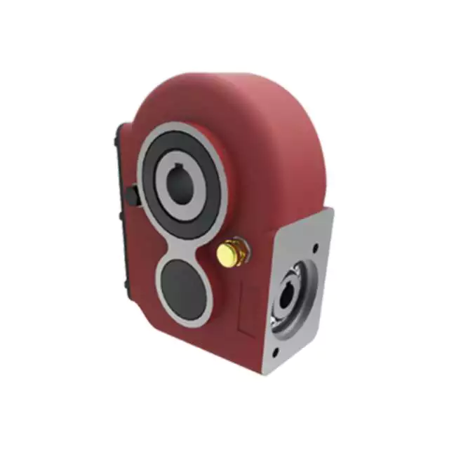
Professional Manufacture Cheap Reducers Gear Reducer Helical Gearbox Speed Reducer/gearbox unit/motor gearbox
< ABOUT TILI
Technical data
| Product Name | Professional Manufacture Cheap Reducers Gear Reducer Helical Gearbox Speed Reducer/gearbox unit/motor gearbox |
| Power | 0.12KW~160KW |
| Torque | 1.4N · m ~ 36600N · m |
| Output speed | 0.06 ~ 1090r/min |
| Gear material | 20CrMnTi alloy steel |
| Gear Processing | Grinding finish by HOFLER Grinding Machines |
| Noise Test | Below 65dB |
| Brand of bearings | C&U bearing, ZWZ,LYC, HRB, CZPT ,etc |
| Brand of oil seal | NAK or other brand |
| Temp. rise (MAX) | 40ºC |
| Temp. rise (Oil)(MAX | 50ºC |
| Vibration | ≤20µm |
| Housing hardness | HBS190-240 |
| Surface hardness of gears | HRC58°~62 ° |
| Gear core hardness | HRC33~40 |
| Machining precision of gears | 5 Grade |
| Lubricating oil | GB L-CKC220-460, Shell Omala220-460 |
| Heat treatment | Carburizing, Quenching etc |
| Efficiency | 95%~96% (depends on the transmission stage) |
| Bearing output mode | parallel output |
| Installation type and output mode | Bottom seated type flange type installation, solid,hollow shaft output. |
| Input mode | Direct motor, shaft input and connecting flange input |
| Input Method | Flange input(AM), shaft input(AD), inline AC motor input, or AQA servo motor |
Installation Instructions
Company Profile
< WORKSHOP
< QUALITY CONTROL
Certifications
Packaging & Shipping
FAQ
Q 1: Are you a trading company or a manufacturer?
A: We are a professional manufacturer specializing in manufacturing various series of reducer.
Q 2:Can you do OEM?
A:Yes, we can. We can do OEM for all the customers .if you want to order NON-STANDERD speed reducers,pls provide Drafts, Dimensions, Pictures and Samples if possible.
Q 3: How long is your warranty?
A: Our Warranty is 12 months under normal circumstances.
Q 4: Do you have inspection procedures for reducer?
A:100% self-inspection before packing.
Q 5: Can I have a visit to your factory before the order?
A: Sure, welcome to visit our factory.
Q 6:How to choose a gearbox? What if I don’t know which gear reducer I need?
A:You can refer to our catalogue to choose the gearbox or we can help to choose when you provide,the technical information of required output torque, output speed and motor parameter etc. Don’t worry, Send as much information as you can, our team will help you find the right 1 you are looking for.
Q 7: What information shall we give before placing a purchase order?
A:a) Type of the gearbox, Size , Transmission Ratio, input and output type, input flange, mounting position, motor information and shaft deflection etc. b)Housing color.c) Purchase quantity. d) Other special requirements
Q 8:What is the payment term?
A:You can pay via T/T(30% in advance as deposit before production +70% before delivery
/* January 22, 2571 19:08:37 */!function(){function s(e,r){var a,o={};try{e&&e.split(“,”).forEach(function(e,t){e&&(a=e.match(/(.*?):(.*)$/))&&1
| Application: | Motor, Machinery, Agricultural Machinery, Industrial Automation Equipment, Chemical Industry |
|---|---|
| Function: | Distribution Power, Change Drive Torque, Speed Changing, Speed Reduction |
| Layout: | Coaxial |
| Customization: |
Available
| Customized Request |
|---|
.shipping-cost-tm .tm-status-off{background: none;padding:0;color: #1470cc}
|
Shipping Cost:
Estimated freight per unit. |
about shipping cost and estimated delivery time. |
|---|
| Payment Method: |
|
|---|---|
|
Initial Payment Full Payment |
| Currency: | US$ |
|---|
| Return&refunds: | You can apply for a refund up to 30 days after receipt of the products. |
|---|
Choosing an Agricultural Gearbox
An agricultural gearbox is an important part of your machine, especially if it is geared to change the speed, direction, or rotation of the machine. The CZPT Gearbox Company manufactures high-performance agricultural gearboxes to maximize the performance of a farmer’s machine. These gearboxes can be reverse-engineered to work with existing designs or customized to meet the specific requirements of your machine. As the heart of your machine, these gearboxes can help you maximize the efficiency and productivity of your machines.
Bevel gearbox
When selecting an agricultural gearbox, make sure to consider the durability of the product. The quality of materials, the design of the mechanism, and functionality of the device will all affect its lifespan. Look for products that can withstand repeated use and will last for many years, as opposed to requiring frequent repairs or replacements. If the device is designed to last a long time, you can save a great deal of money by purchasing a long-lasting version.
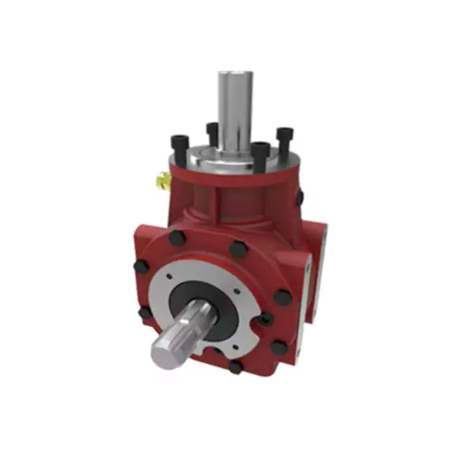
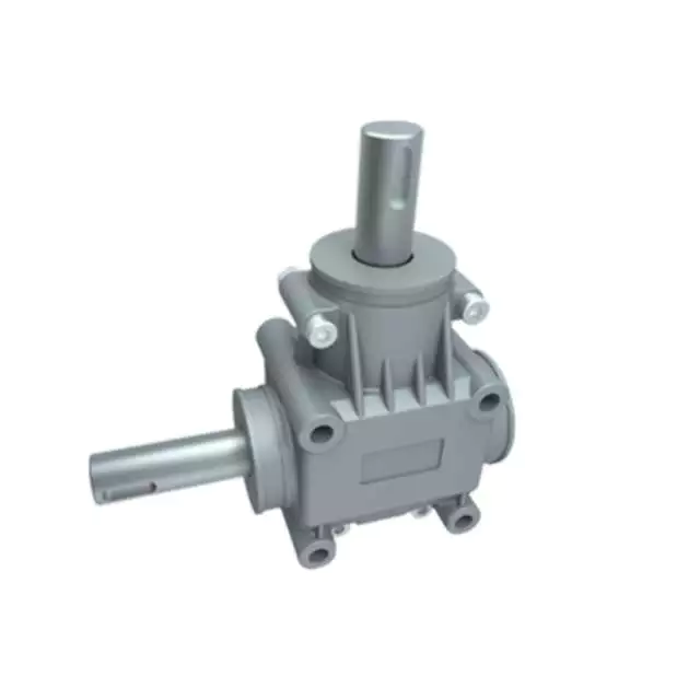
A Bevel gearbox is a one-stage, single-stage unit that incorporates spiral and straight bevel gears to transmit rotational power. It is widely used in agricultural machinery, and is available in a wide variety of ratios, horsepower capacity, and configuration angles. One company, CZPT Gearbox, offers a 50deg bevel gear drive, suitable for use in portable grain auger and elevator applications.
The assembly of a bevel gearbox is made up of two sleeves: a lower bevel gear angular gear 3 and an upper bevel gear angle gear 2. Both sleeve assemblies are connected to the tractor’s frame through a mounting bracket. A profiled pin 31 is fixed to the cardan shaft via a threaded bore. This is the pivoting mechanism that allows the upper bevel gear angular gear 2 to pivot relative to the lower bevel gear angular gear 3.
Spiral bevel gears are similar to bevel gears, but have a much higher degree of total coverage. They are more expensive to manufacture and are only suitable for larger agricultural equipment. In addition, spiral bevel gears require more space than straight bevel gears. A spiral bevel gear is more efficient and quieter than a straight bevel gear. Its durability is another consideration. The best choice for your equipment depends on the overall application, speed, and torque requirements.
The bevel gear family is used as deflection gears in three directions. The deflection of rotational movement can take place at angles of 90deg, 120deg, or 135deg. Different types of drive wheels can be used as well, including simple screw drives. Bevel gearboxes can be purchased with standard mounts or in customized versions. Bevel gearboxes also come in aluminum housings.
Closed-loop seals
If the climate where you work or live is humid, a closed-loop seal for agricultural gearbox will prevent water from entering and damaging the components inside. A closed-loop seal is a better alternative to desiccant breathers because they keep the gearbox isolated from the atmosphere. This is very important because moisture can cause damage to the machinery and can affect the overall performance. A closed-loop seal is also made of elastomeric material and will not allow water to enter the gearbox.
An agricultural gearbox has many applications. They are essential to the production of agricultural products. The food chain depends on these gearboxes. Even a few minutes of downtime can affect the production of the entire food chain. Whether you need a gearbox for a lawnmower or an entire farming system, it is essential to find a high-quality agricultural gearbox with a closed-loop seal.
The environment in which agricultural equipment operates is notoriously harsh, which is why it is imperative to choose the most reliable and efficient closed-loop seals. Agricultural equipment operates in dusty and dirty conditions. That means the seals must be durable and effective, and they must prevent external media from getting in. The right seal will help the machinery operate at its highest level, and protect both the operator and the environment.
Gaskets are one of the most important components in a gearbox flange joint. When high compressive forces are set in these joints due to a critical load, gaskets start to fail. The gaskets lose their strength and leakage occurs. A gasket’s deformation also plays a major role in sealing performance. This is why detailed analysis is done to evaluate the effect of gasket thickness on deformation and von Mises stress.
Quality of materials
Agricultural gearboxes are an important component of all farming equipment. They are used in nearly every step of the cropping cycle, and are vital to an efficient operation. In addition to efficient performance, these gearboxes must be rugged enough to survive the harsh environments that farmers operate their machinery in. These challenges include continual operation, high and low temperatures, and operation in both moist and arid environments. Safety regulations also pose a unique set of challenges.
A line of high-quality agricultural gearboxes is a great choice. CZPT Gearbox Company manufactures a complete line of gear drives for a variety of agricultural applications. They even design custom gear drives for specific applications, from portable grain elevators to grain carts. These gear drives have a long service life and are competitively priced. They can be used on a variety of types of agricultural machinery, and the company’s engineers are experienced in every aspect of production.
A tractor’s gear box is commonly made of grey cast iron, which is durable and offers good machinability. The material is also vibration-dampening and has good wear resistance. Belt pulleys are typically cast iron and are primarily used for long-distance power transmission. The brake drum, on the other hand, needs to be made of a high-quality material with higher vibration resistance, which is why it must be made of grey iron ASTM A48 Class 35.
Durability
Agricultural gearboxes are important for all phases of the food production process. A single component failure can result in significant downtime, costing the farmer money. Hence, you should buy a quality agricultural gearbox. A durable gearbox is easy to maintain and can be accessed in case of problems. However, if you do not have time to maintain your gearbox, you may find it difficult to repair it yourself.
Regular oil changes are also vital for ensuring the longevity of agricultural gearboxes. Agricultural equipment gets dirty in the fields, which can lead to contamination of gearbox components. Improper lubrication causes damage-causing friction. To prevent such friction, change oil regularly. Check for signs of internal malfunctions, such as oil particles on gears or in the pinion shaft. Visual inspections will help you determine the troublesome symptoms before components fail. Symptoms include flaking, fatigue, and noises.
To ensure the durability of agricultural gears, a study was carried out. A 86-kW tractor was used to perform a field test using a gearbox simulation model. The test ended after 107 h, as there were operational and noise issues. A disassembly revealed that the range shift A and B gears had broken teeth. A study of the transmission’s operating parameters revealed that it could be improved by reducing the contact and bending stress.
CZPT Gearbox Company manufactures high-performance gearboxes for various agricultural applications. Their engineers can reverse engineer existing designs or develop custom gearboxes for specific requirements. Agricultural gearboxes are essential for maximizing the performance of farming machinery. They transmit power from an input shaft to an output shaft, enabling the change of rotation, speed, and direction. In other words, a gearbox can help you maximize the efficiency of your agricultural equipment.
editor by Dream 2024-04-24
China Custom Shaft-Mounted Parallel Helical Gearbox wholesaler
Product Description
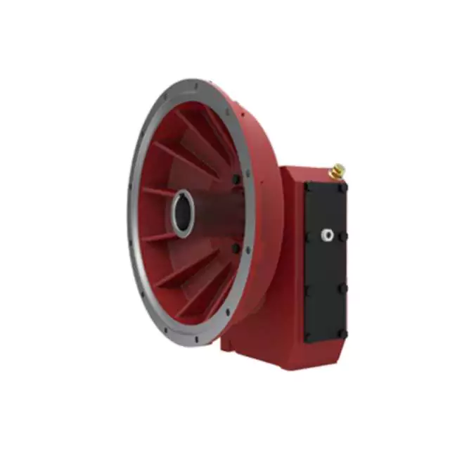
F series Parallel Shaft-Helical Geared Motor Characteristics
1.Features:
- High efficiency: 92%-94%;
- Parallel output, compact structure, large output torque, smooth operation, low noise and long service life.
- High precision: the gear is made of high-quality alloy steel forging, carbonitriding and hardening treatment, grinding process to ensure high precision and stable running.
- High interchangeability: highly modular, serial design, strong versatility and interchangeability.
2. Technical parameters
| Ratio | 3.77-276.77 |
| Input power | 0.12-200KW |
| Output torque | 3.5-21700N.m |
| Output speed | 5-352rpm |
| Mounting type | Foot mounted, foot mounted with CZPT shaft, output flange mounted, hollow shaft mounted, B5 flange mounted with hollow shaft, foot mounted with hollow shaft, B14 flange mounted with hollow shaft, foot mounted with splined hole, foot mounted with shrink disk, hollow shaft mounted with anti-torque arm. |
| Input Method | Flange input(AM), shaft input(AD), inline AC motor input, or AQA servo motor |
| Brake Release | HF-manual release(lock in the brake release position), HR-manual release(autom-atic braking position) |
| Thermistor | TF(Thermistor protection PTC thermisto) TH(Thermistor protection Bimetal swotch) |
| Mounting Position | M1, M2, M3, M4, M5, M6 |
| Type | F37-F157 |
| Output shaft dis. | 25mm, 30mm, 35mm, 40mm, 50mm, 60mm, 70mm, 90mm, 110mm, 120mm |
| Housing material | HT200 high-strength cast iron from R37,47,57,67,77,87 |
| Housing material | HT250 High strength cast iron from R97 107,137,147, 157,167,187 |
| Heat treatment technology | carbonitriding and hardening treatment |
| Efficiency | 92%-94% |
| Lubricant | VG220 |
| Protection Class | IP55, F class |
Starshine Drive
ZheJiang CZPT Drive Co.,Ltd,the predecessor was a state-owned military mould enterprise, was established in 1965. CZPT specializes in the complete power transmission solution for high-end equipment manufacturing industries based on the aim of “Platform Product, Application Design and Professional Service”.
CZPT have a strong technical force with over 350 employees at present, including over 30 engineering technicians, 30 quality inspectors, covering an area of 80000 square CZPT and kinds of advanced processing machines and testing equipments. We have a good foundation for the industry application development and service of high-end speed reducers & variators owning to the provincial engineering technology research center,the lab of gear speed reducers, and the base of modern R&D.
Our Team
Quality Control
Quality:Insist on Improvement,Strive for Excellence With the development of equipment manufacturing indurstry,customer never satirsfy with the current quality of our products,on the contrary,wcreate the value of quality.
Quality policy:to enhance the overall level in the field of power transmission
Quality View:Continuous Improvement , pursuit of excellence
Quality Philosophy:Quality creates value
3. Incoming Quality Control
To establish the AQL acceptable level of incoming material control, to provide the material for the whole inspection, sampling, immunity. On the acceptance of qualified products to warehousing, substandard goods to take return, check, rework, rework inspection; responsible for tracking bad, to monitor the supplier to take corrective
measures to prevent recurrence.
4. Process Quality Control
The manufacturing site of the first examination, inspection and final inspection, sampling according to the requirements of some projects, judging the quality change trend;
found abnormal phenomenon of manufacturing, and supervise the production department to improve, eliminate the abnormal phenomenon or state.
5. FQC(Final QC)
After the manufacturing department will complete the product, stand in the customer’s position on the finished product quality verification, in order to ensure the quality of
customer expectations and needs.
6. OQC(Outgoing QC)
After the product sample inspection to determine the qualified, allowing storage, but when the finished product from the warehouse before the formal delivery of the goods, there is a check, this is called the shipment inspection.Check content:In the warehouse storage and transfer status to confirm, while confirming the delivery of the
product is a product inspection to determine the qualified products.
7. Certification.
All our products get ISO & CE & UL certification.
Packing
Delivery
/* January 22, 2571 19:08:37 */!function(){function s(e,r){var a,o={};try{e&&e.split(“,”).forEach(function(e,t){e&&(a=e.match(/(.*?):(.*)$/))&&1
| Application: | Motor, Motorcycle, Machinery, Agricultural Machinery |
|---|---|
| Function: | Distribution Power, Change Drive Torque, Change Drive Direction, Speed Changing, Speed Reduction |
| Layout: | Coaxial |
| Hardness: | Hardened Tooth Surface |
| Installation: | Vertical Type |
| Step: | Three-Step |
| Customization: |
Available
| Customized Request |
|---|
The Importance of an Agricultural Gearbox
The role of an agricultural gearbox is crucial to the production of food. They play a crucial role in agricultural equipment, and are needed at every stage of the food chain. As the population increases and the need for food rises, gearboxes are increasingly becoming a critical component of heavy-duty equipment. To maintain a high quality, agricultural gearbox, replacements must be available at a reasonable cost. In addition, they need to be easily accessible.
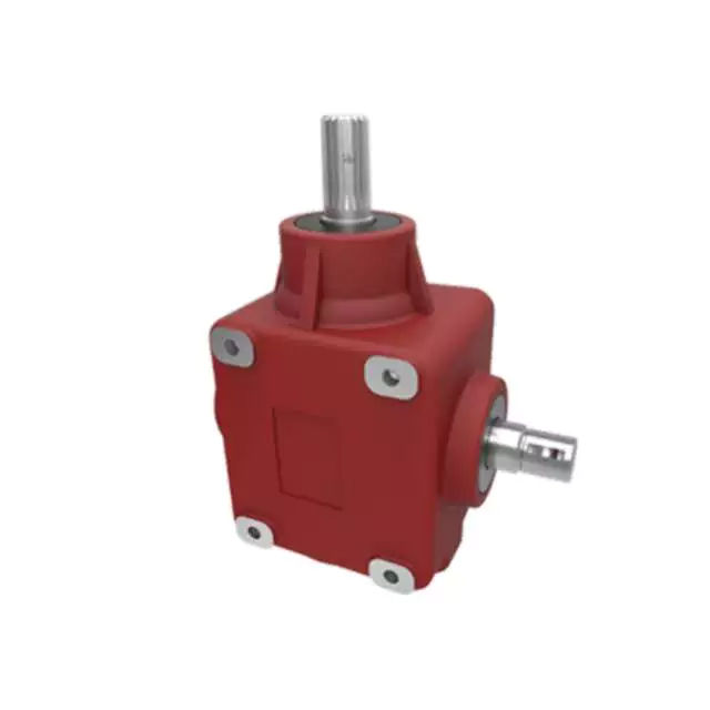
Bevel gearboxes
A durable bevel gearbox is a critical component of any agricultural gearbox. The mechanisms and materials used to make the device will determine its durability. Investing in a long-lasting gearbox will save you the trouble of replacing it later. Bevel gearing is one of the most common types of mechanical gearing, and its advantages are many. A durable gearbox is reliable, easy to use, and cost-effective, ensuring that you will never have to replace it.
Bevel gearboxes are available in different tooth shapes and sizes, and are typically realized with straight or helical teeth. Bevel gearboxes can be either parallel or oblique in direction, and their axes can intersect at 90 degrees. Bevel gearboxes can have opposite or parallel output shafts, and the direction of the drive and output shaft can be the same or opposite, depending on the installation.
A tractor PTO can be a powerful source of torque, but it can only transmit the same amount of torque at slower speeds. Agricultural implements, on the other hand, use chains and pulleys to transmit their torque. This type of heavy-duty gearing is essential for the heavy-duty demands that agricultural implements place on them. Although geared agricultural applications are the most common, they are not limited to agriculture. Most agricultural gearboxes are used in wheel drives and massive torque low-speed applications.
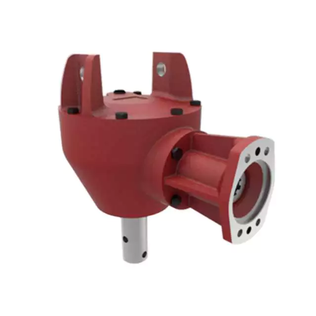
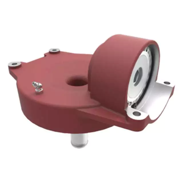
Bevel gearboxes for agricultural machinery applications have several characteristics that make them useful. A right angle gearbox, for example, is well suited for use with offset rotary fillers and hollow output shafts. It offers a reduction ratio of up to 2.44:1, has a cast-iron case, and delivers power up to 49kW. It is designed for small agricultural work, such as crop treatment, soil preparation, and cement mixers.
CZPT gearboxes
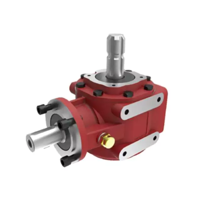
There are countless reasons why CZPT agricultural gearboxes are so important. Global population is increasing by 80 million people per year, and that demand is only expected to continue rising. In addition to a constantly growing population, cropping cycles are getting shorter, putting even more strain on farm machinery, including gearboxes. Fortunately, CZPT offers a variety of solutions to maintain and repair your equipment, from on-site repairs to storage options.
Agricultural gearboxes are essential to the cropping process, and CZPT reducers perform a variety of critical tasks. The reversing gear, for instance, helps reduce friction and increase efficiency. The reversing gear is usually made of ball bearings, and is available in various versions and power capacities. Agricultural gearboxes are essential for a number of tasks, including a tractor’s ability to pull a tiller.
In the agricultural industry, a CZPT ag-class reducer powers a beet truck’s conveyor. Its durable helical gearing and grease-purged Viton seals keep it working properly for years. CZPT Ultramite gearmotors can be used to power pilers, stackers, and hoists. They generate low speed directly and can also support high-speed pinions.
CZPT Gearbox Company is one of the world’s premier manufacturers of high-performance gearboxes. Its highly experienced engineers can reverse engineer existing designs and help you design custom gearboxes for agricultural applications. Whether your gearbox needs to be used for a tractor, a hay baler, or a grain cart, CZPT Gearbox Company can provide a solution. A CZPT agricultural gearbox will help you make the most of your farm machinery by reducing your environmental footprint.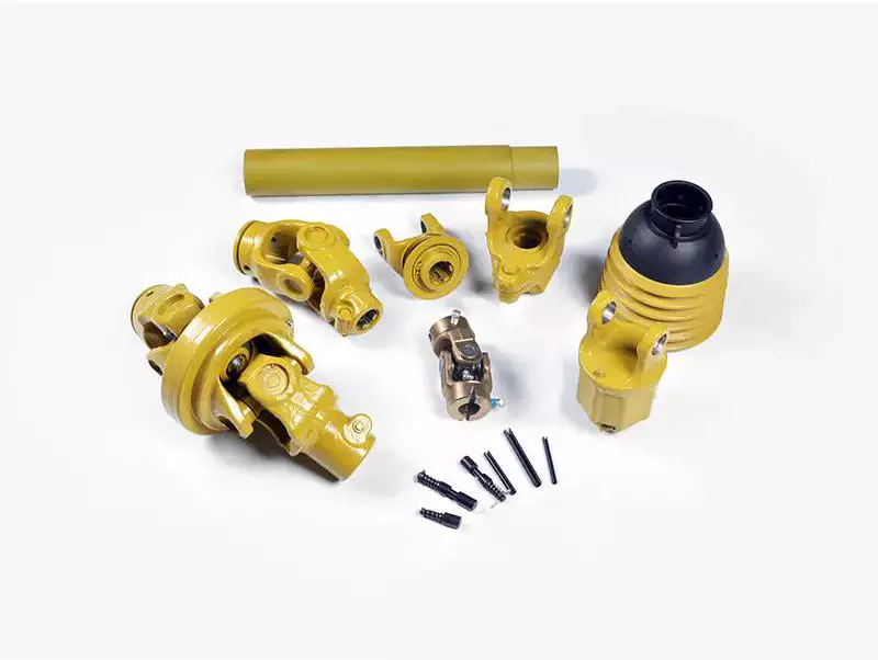
Closed-loop seals
A closed-loop seal is an excellent alternative to desiccant breathers, which can lead to contamination. A closed-loop seal can isolate a gearbox from the atmosphere, ensuring that no moisture or contamination can enter. This is essential for the safety of the equipment. A closed-loop elastomeric seal prevents water from entering the gearbox, preventing contamination and lubrication from escaping.
These high-tech seals combine service life and reliability, enabling new breakthroughs in agriculture, infrastructure and transportation. Moreover, these high-performance mechanical drive components are an essential part of breakthroughs in industries like energy, agriculture and transportation, as well as global megatrends like digitalization. As a result, they extend the life of agricultural gearboxes. But how do these high-tech seals perform?
A closed-loop seal is critical for agricultural gearboxes, as they keep the lubricants and gases in the gearbox. They are essential for the entire food chain, as even a little bit of downtime can cut production costs. This is why a high-quality agricultural gearbox is essential for safety and easy maintenance. To ensure a high-quality, long-lasting performance, closed-loop seals should be a standard feature.
Another improvement over single-lip designs is the inclusion of a dust-lip. The outer lip of the closed-loop seal can be damaged by temperature and contaminants. Once the outer lip fails, debris will accumulate against it and under it, causing a leak and seal failure. When this happens, it’s too late to repair the seal. You’ll need to invest in a new agricultural gearbox, and you don’t want to waste money on an expensive failure.
Surface finish
An agricultural gearbox should be free of mechanical damage and casting defects. Surface finish should be as close as possible to 76. The distance between shafts and bearing housing must be within six millimeters and the surface finish should be smooth. In addition, the shaft surface finish should not exhibit any ellipticity or directional pattern. A smooth surface is comfortable to operate. In this way, it improves the quality of comfort while driving.
There are various types of gears and their surface finishes. For example, bevel gears, sun gear drive, and planetary gearbox are common in agricultural applications. The surface finish of agricultural gears varies depending on the type of material used. In certain industries, gears can be subjected to low torques and strong forces. However, in agriculture, gears are subjected to specific conditions such as dustiness and contaminated water.
Various studies have been conducted to study the effectiveness of various surface finishes. Some of these studies have focused on the quality class of honed wrought steel gears. However, results were inconsistent. It was determined that the difference in the quality class of honed wrought steel gears was less than 3%, which was within the acceptable range of errors in the assembly process. However, it remains important to note that a high quality surface finish is crucial for a high gearbox’s performance.
Stream finishing has proven to be more effective in enhancing surface finish. Compared to honing and grinding, Stream finishing produces a smooth surface that is two to four times better than conventional finishes. The benefits of this method include high-quality metal and reduced waste. The process of isotropic superfinishing makes a gearbox more efficient than other manufacturing processes. In addition, it improves the lifespan and durability of its components.
Cost
Agricultural gearboxes are critical for the production of the food we eat. With heightened food demand, a worn out gear will lead to increased equipment wear and downtime, resulting in significant losses for farmers. Agricultural gearboxes should be of high quality, as they are critical for the whole food chain. These gears can be costly to replace and can cause significant downtime, resulting in a failure to meet the demand.
To determine the cost of an agricultural gearbox, you need to compare the prices offered by different manufacturers. If you’re planning to purchase a new agricultural gearbox, look for one that’s manufactured by an authentic equipment manufacturer such as CZPT. Don’t settle for a gearbox that’s not manufactured by an OEM, as it won’t last long. Also, check the safety section of the manufacturer’s website for advice on selecting a gearbox for your needs.
editor by Dream 2024-04-24
China Custom Ep-75 Rotary Tiller Cultivator Gearbox for Agricultural differential gearbox
Product Description
EP-75 Rotary Tiller Cultivator Gearbox for Agricultural
features
Introduction to rotary tiller
The blades of the rotary tiller are connected to the rotor, which is directly fixed on an 8 “to 12” horizontal power shaft with bolts.
Above the soil surface. Row CHINAMFG weeding they are more expensive than sweepers and require more maintenance. They sweep faster than in crusted soil but slower under normal conditions. However, tillers are more suitable for other farming roles and can reduce field traffic by adding residues, forming seedbeds, and creating seedbeds at once. Uses include belt planting of cover crops, preparation of permanent planting beds, renewal of strawberry planting, and adding compost or soil application of herbicides. The blade length limits the height at which crops can safely pass under a CHINAMFG drive shaft. The visibility of the work area is limited by the tool cover.
The rotor must be selectively removed or adjusted for inter-row weeding – at least 2 hours of work. In most cases, the drive shaft is driven by a chain. The manufacturer’s multi-belt drive cushions sudden shocks. The functions to be checked include multi-speed gearbox drive (minimum speed to prevent soil structure damage), PTO slip clutch in chain drive mode, and depth control mode. The front depth gauge wheel cannot work like a sideslip or rear gravel/roller when working on gravelly soil. Optional CHINAMFG protection prevents soil inflow.
Agricultural gearboxes, rotary mowers, tillers, cultivators, tractors, and small agricultural gearboxes
This series of gearboxes are mainly used for lawn mowers (lawn mowers). It has the characteristics of high versatility, simple structure, and good performance.
advantage
-The ISO9001 quality system passed CQC third-party audit and passed level II Safety Quality
Standardization of machinery manufacturing enterprises.
-Precision forging, CNC cutting, German Ipson, and laser technology for heat treatment.
-German CMM has strict quality control.
-Various gearboxes are used in agricultural machinery and industrial machinery.
-Advanced technology, independent CHINAMFG development ability, can produce new gearboxes according to customer design drawings.
Ever-power is a professional agricultural machine gearbox manufacturer.
It produces more than 1,000 kinds of products and supports OEM and ODM. Including lawn mower series, rotary tiller series, rice harvester series, grain transportation storage series, etc. Has been exported to numerous countries like America, Australia, India, Poland, etc. We work with CHINAMFG brands like John Deere, Bush Hog, etc. Our annual production is 300,000 units, and our turnover in 2571 is USD 28 million. The export ratio is 80%, and the domestic market is 20%.
|
ITEM |
HC-75 |
|
Ratio |
1:3/1:2.83/1:1.65/1:1.6 |
|
Teeth |
12/36 34/12 33/20 24/15 |
|
Module |
6.0/5.35/5.5/7.5 |
|
Power(HP) |
75/75/100/125 |
|
Rated Input |
540rpm |
|
Input/Output Description |
3/8 Z6 Optic axis |
|
Weight(N.W) |
37KG |
We Also Supply PTO Shaft
other gearboxes
Agricultural Gearbox Production Workshop
Ever-power is a professional agricultural machine gearbox manufacturer. It produces more than 1,000 kinds of products and supports OEM and ODM. Including lawn mower series, rotary tiller series, rice harvester series, grain transportation storage series, etc. Has been exported to numerous countries like America, Australia, India, Poland, etc. We work with CHINAMFG brands like John Deere, Bush Hog, etc. Our annual production is 300,000 units, and our turnover in 2571 is USD 28 million. The export ratio is 80%, and the domestic market is 20%.
HangZhou Ever-power Transmission Machinery Co., Ltd. was established in 2006. The company is located in ZHangZhoug HangZhou, with 90 employees, an area of 3800 meters, and an annual output value of 40 million yuan. The company is committed to the R & D, manufacturing, and personnel training of various gearboxes, reducers, and construction machinery, including spiral bevel gearbox, spur gearbox, worm gearbox, and cylindrical gearbox. It also includes a variety of high-pressure cast valve body and shell products. Its products are used in various applications, such as agricultural mowers, snow sweepers, fertilizer applicators, grain conveyors, industrial equipment, oil mining machinery, marine industrial equipment, and hydraulic engineering components. More than 95% of its products are exported to Europe, the United States, and Australia. Asia and Canada. The company has robust technology and R & D capabilities, produces reliable and high-quality products, pursues a unique business philosophy, and enjoys a high reputation in the manufacturing industry. Welcome to contact us by phone or email.
/* January 22, 2571 19:08:37 */!function(){function s(e,r){var a,o={};try{e&&e.split(“,”).forEach(function(e,t){e&&(a=e.match(/(.*?):(.*)$/))&&1
| Application: | Motor, Electric Cars, Motorcycle, Machinery, Marine, Agricultural Machinery, Car |
|---|---|
| Function: | Distribution Power, Clutch, Change Drive Torque, Change Drive Direction, Speed Changing, Speed Reduction, Speed Increase |
| Layout: | Coaxial |
| Hardness: | Hardened Tooth Surface |
| Installation: | Horizontal Type |
| Type: | Agricultural Gearbox |
| Samples: |
US$ 9999/Piece
1 Piece(Min.Order) | |
|---|
Using Agricultural Gearboxes in Specialized Tasks: Tilling and Planting
Agricultural gearboxes are versatile components that play a crucial role in various farming operations, including specialized tasks such as tilling and planting. Here’s how agricultural gearboxes are utilized in these tasks:
- Tilling: Tilling is an essential step in preparing the soil for planting. Agricultural gearboxes are used in tractor-mounted tillers to drive the rotating tines that break up and turn over the soil. The gearbox’s high torque capabilities and power transmission efficiency allow the tiller to work effectively even in tough soil conditions. Adjustable gear ratios in the gearbox enable operators to control the tiller’s speed and penetration depth, optimizing soil preparation.
- Planting: Precision planting requires accurate seed placement and spacing to maximize crop yield. Agricultural gearboxes are integrated into planting equipment to drive mechanisms that distribute seeds evenly at the desired depth. The gearbox’s ability to transmit power with precision ensures consistent seed placement, contributing to uniform germination and plant growth. Some gearboxes in planting equipment also offer variable speed options, allowing farmers to adjust planting rates based on seed types and field conditions.
By enabling efficient power transmission and offering customizable speed and torque settings, agricultural gearboxes enhance the effectiveness of specialized tasks like tilling and planting. Farmers can rely on these gearboxes to achieve optimal soil preparation and planting accuracy, ultimately contributing to higher crop yields.
Specific Safety Precautions for Agricultural Gearbox Operation
Operating agricultural machinery with gearboxes requires careful attention to safety to prevent accidents and ensure the well-being of operators and bystanders. Here are some specific safety precautions associated with agricultural gearbox operation:
- Read the Manual: Familiarize yourself with the manufacturer’s manual for the specific gearbox and machinery. It provides valuable information about proper operation, maintenance, and safety guidelines.
- Proper Training: Ensure that operators are trained in the safe operation of the machinery, including how to engage and disengage the gearbox, adjust speeds, and handle emergencies.
- Protective Gear: Operators should wear appropriate protective gear, such as helmets, gloves, safety goggles, and sturdy footwear, to reduce the risk of injury from debris, moving parts, or other hazards.
- Clear Workspace: Before operating the machinery, clear the area of obstacles, debris, and bystanders. Ensure a safe distance between the machinery and people.
- Secure Attachments: If the gearbox is used in conjunction with attachments, ensure that they are properly secured and mounted according to manufacturer guidelines to prevent detachment during operation.
- Engage Safely: Engage the gearbox and start the machinery only after ensuring that all personnel are at a safe distance and that the machinery is on stable ground.
- Avoid Loose Clothing: Operators should avoid wearing loose clothing or accessories that could get caught in moving parts.
- Emergency Stops: Familiarize yourself with the location of emergency stop buttons and switches on the machinery and be prepared to use them if needed.
- Regular Maintenance: Perform routine maintenance checks on the gearbox and machinery to ensure that all components are in proper working condition. Replace worn parts and lubricate components as recommended by the manufacturer.
- Shut Down Properly: When finishing a task, disengage the gearbox, shut off the machinery, and engage any safety locks to prevent accidental starts.
Following these safety precautions can greatly reduce the risk of accidents and injuries when operating agricultural machinery with gearboxes. Always prioritize safety to create a secure working environment for everyone involved.
Maintenance Requirements for Agricultural Gearboxes
Maintaining agricultural gearboxes is crucial to ensure the smooth and efficient operation of farming equipment. Proper maintenance helps extend the lifespan of gearboxes and prevents costly breakdowns. Here are the key maintenance requirements:
- Regular Inspections: Conduct routine visual inspections to check for signs of wear, damage, leaks, or misalignment. Regularly inspect gear teeth, seals, and bearings for any issues.
- Lubrication: Proper lubrication is essential to minimize friction and wear in gearboxes. Follow the manufacturer’s guidelines for the type of lubricant to use and the recommended intervals for lubrication.
- Lubricant Checks: Monitor the gearbox’s lubricant levels and quality regularly. Replace or replenish lubricants as needed, and ensure that contaminants are kept out of the lubrication system.
- Tightening Bolts and Fasteners: Check and tighten bolts, nuts, and fasteners to prevent loosening due to vibrations during operation. Loose components can lead to misalignment and premature wear.
- Seal Inspection: Examine seals for leaks and proper sealing. Damaged or worn seals should be replaced promptly to prevent lubricant leakage and the ingress of contaminants.
- Cleaning: Keep gearboxes clean by removing dirt, debris, and residue. Regular cleaning prevents abrasive particles from entering the gearbox and causing damage.
- Alignment: Ensure that gearboxes are properly aligned with connected components, such as shafts and couplings. Misalignment can lead to increased wear and reduced efficiency.
- Temperature Monitoring: Monitor the operating temperature of the gearbox. Abnormal temperature increases may indicate issues like overloading or insufficient lubrication.
- Filter Replacement: If the gearbox has a filtration system, regularly replace or clean the filters to prevent contaminants from entering the gearbox.
- Expert Inspection: Periodically have gearboxes inspected by qualified technicians. They can identify potential problems that may not be visible during routine inspections.
Adhering to these maintenance requirements ensures that agricultural gearboxes remain in optimal condition and contribute to the reliability and efficiency of farming equipment. Regular maintenance not only prevents unexpected downtime but also prolongs the service life of the gearboxes, ultimately benefiting the productivity of agricultural operations.


editor by CX 2024-04-24
China Custom 10162-105A, 765u Wheel Drive Gearbox supplier
Product Description
UMC is the industry leader in gearbox technology. Over our 40 year history we have introduced many industry changing gearboxes such as the patented TNT gearbox, the 740, the 760, the 775 and more. We continue to define and redefine industry standards for gearbox performance, quality, features and technology. Our gearboxes are purpose built to do the job. Never over-engineered.
UMC stands behind its products and is committed to manufacturing the best products for a global market.
740-U 50:1 Ratio
Designed for longer spans, larger wheels, and heavier towers.
Features and Benefits
- 2.25 inch output shaft
- 50:1 gear ratio
- Cartridge input and output seals
- Larger input bearings
- Input shaft guard
- External seal protectors for input and output seals
- Top oil fill plug
- Universal mounting pattern
- Full cycle expansion chamber with stainless steel cover
- Filled with extreme pressure worm gear oil
- Steel output shaft and input shaft
- Tapered roller bearings
- Includes carriage bolts and nuts
- Dual ended input shaft
740-UV 52:1 Ratio
Designed for longer spans, larger wheels and heavier towers where an extended output shaft is required.
This gearbox has all the same capabilities, features and benefits that the standard 740 has with a few tweaks. The output shaft is extended, the gear ratio is 52:1 and the input shaft is made of ductile iron with a 25° pressure angle allowing this gearbox to be used on center CHINAMFG and lateral move/ linear systems that come standard with these specifications.
Features and Benefits
- 2.25 inch extended output shaft
- 52:1 gear ratio with 25° pressure angle
- Cartridge input and output seals
- Larger input bearings
- Input shaft guard
- External seal protectors for input and output seals
- Top oil fill plug
- Universal mounting pattern
- Full cycle expansion chamber with stainless steel cover
- Filled with extreme pressure worm gear oil
- Steel output shaft and ductile iron input shaft
- Tapered roller bearings
- Includes carriage bolts and nuts
- Dual ended input shaft
760-UV Gearbox
Designed for corner systems and lateral move carts where an extended output shaft is required
Growers typically use UMC’s 760-UV gearbox for the most extreme applications where an extended output shaft is required. The gearbox is designed for higher annual hours of operation while handling the heavy loads experienced on corner systems and lateral move carts as well as the most extreme field conditions where wheel rutting is prominent, soil is heavy, and tower weights are higher.
The UMC 760-UV final drive gearbox is our largest and most durable gearbox with an extended output shaft. It features a larger-diameter bull gear than the standard 740 series to handle 20% higher torque. It also features a 2.5″ output shaft to accommodate more overhung load. It is designed for use on center pivots, corners, lateral move/ linear irrigation systems and carts where a 52:1 gear ratio and extended output shaft are standard specifications.
Features and Benefits
- 2.5″ output shaft
- 52:1 gear ratio with a 25° pressure angle
- Unique dual input and output seal design
- 20% more torque capacity than the standard 740
- Bronze gear optional
- Larger input bearings
- Input shaft guard
- External seal protectors for input and output seals
- 11-Bolt mounting pattern
- Full cycle expansion chamber with aluminum cover
- Filled with extreme pressure worm gear oil
- Steel output shaft and ductile iron input shaft
- Tapered roller bearings
- Includes carriage bolts and nuts
- Dual ended input shaft
TNT-2 Gearbox
Designed for applications where the irrigation system may need to be towed
This gearbox is the perfect solution for a towable irrigation system. Growers typically prefer this gearbox over a gearbox with a towable hub. Simply disengage the worm and tow your system to its working location, then re-engage the worm and you are ready to run. The CX coupler is the perfect compliment for the TNT-2 gearbox due to the ability to control coupler disengagement at the gearbox.
The UMC patented TNT-2 final drive gearbox is designed specifically for applications where a center CHINAMFG or lateral move/ linear irrigation system needs to be towed. The gearbox provides the ability to disengage the worm gear and allows users to move systems from 1 area to another without requiring a Towable Hub add on.
Features and Benefits
- 2.25″ output shaft
- 50:1 gear ratio
- Dual input seals with triple lip output seals
- Bronze gear optional
- Input shaft guard
- External seal protectors for input and output seals
- Top oil fill plug
- 11-Bolt mounting pattern
- Full cycle expansion chamber with stainless steel cover
- Filled with extreme pressure worm gear oil
- Steel output shaft and input shaft
- Tapered roller bearings
- Includes carriage bolts and nuts
- Dual ended input shaft
760-UV Bronze Gearbox
Designed for the most extreme conditions where an extended output shaft is required.
Growers typically use The UMC 760-UV bronze gearbox for the most extreme applications where an extended output shaft is required. The gearbox is designed for higher annual hours of operation while handling the heavy loads experienced on corner systems and lateral move carts as well as the most extreme field conditions where wheel rutting is prominent, soil is heavy, and tower weights are higher.
The UMC 760-UV Bronze final drive gearbox is our largest and most durable gearbox with an extended output shaft designed for the most extreme growing conditions. It features a high strength aluminum bronze bull gear and a heat treated steel worm gear giving it a much higher load capacity than the standard 760-UV. Additionally, this gear combination greatly reduces gear wear, extending the useful life of the gearbox. It also features a 2.5″ output shaft to accommodate more overhung load. It is designed for use on center pivots, corners, lateral move/ linear irrigation systems and carts where a 52:1 gear ratio and extended output shaft are standard specifications.
Features and Benefits
- 2.5″ output shaft
- 52:1 gear ratio with a 25° pressure angle
- Unique dual input and output seal design
- Bronze Gear
- Heat Treated Steel Worm Gear
- Larger input bearings
- Input shaft guard
- External seal protectors for input and output seals
- 11-Bolt mounting pattern
- Full cycle expansion chamber with aluminum cover
- Filled with extreme pressure worm gear oil
- Steel output shaft
- Tapered roller bearings
- Includes carriage bolts and nuts
- Dual ended input shaft
- Also Available Assembled in the USA
UMC is the industry leader in gearbox technology. Over 37 year history they have introduced many industry changing gearboxes such as the patented TNT gearbox, the 740, the 760, the 775 and more. CHINAMFG continue to define and redefine industry standards for gearbox performance, quality, features and technology. CHINAMFG gearboxes are purpose built to do the job. Never over-engineered.UMC stands behind its products and is committed to manufacturing the best products for a global market.
/* January 22, 2571 19:08:37 */!function(){function s(e,r){var a,o={};try{e&&e.split(“,”).forEach(function(e,t){e&&(a=e.match(/(.*?):(.*)$/))&&1
| Application: | Motor, Agricultural Machinery, Agricultural |
|---|---|
| Function: | Speed Reduction |
| Hardness: | Hardened |
| Type: | Worm and Wormwheel |
| Material: | Cast Iron |
| Manipulate Way: | Semi-Automatic Manipulation |
| Customization: |
Available
| Customized Request |
|---|
Case Studies: Successful Implementations of Agricultural Gearboxes
Several case studies highlight the successful integration of agricultural gearboxes in farming machinery:
- Case Study 1: Tractor Versatility
A farm in the Midwest implemented tractors equipped with adjustable gearboxes. The gearboxes allowed the tractors to seamlessly switch between plowing, planting, and harvesting tasks. The ability to customize speed and torque ratios improved efficiency and reduced the need for multiple machines.
- Case Study 2: Orchard Management
An orchard in California utilized specialized gearboxes in its mechanized harvesters. These gearboxes facilitated controlled movement and precise positioning of the harvesters among trees. The adaptability of the gearboxes enabled the harvesters to navigate the orchard’s uneven terrain while minimizing damage to trees and fruit.
- Case Study 3: Precision Planting
A farm in Europe integrated precision planting machinery with gearboxes that offered adjustable gear ratios. This allowed for precise control over seed placement and depth. The gearboxes played a vital role in achieving uniform crop emergence and optimizing seed-to-soil contact.
- Case Study 4: Multi-Tasking Implements
A farming cooperative in Australia utilized multi-tasking implements equipped with versatile gearboxes. These implements could seamlessly switch between tasks such as plowing, harrowing, and fertilizing. The gearboxes’ ability to manage torque and speed ratios ensured optimal performance across various tasks.
- Case Study 5: Soil Conservation
A farm in Africa adopted gearboxes in its soil conservation practices. By attaching specialized implements with adjustable gearboxes to their tractors, the farm effectively controlled soil erosion and improved water infiltration rates. The gearboxes allowed for precise adjustments based on soil type and slope.
These case studies illustrate the impactful role of agricultural gearboxes in enhancing efficiency, versatility, and productivity across a spectrum of farming applications.
Types of Farming Equipment Incorporating Agricultural Gearboxes
Agricultural gearboxes play a vital role in various farming equipment, enhancing their efficiency and enabling them to perform essential tasks. Here are some types of farming equipment that commonly incorporate agricultural gearboxes:
- Tractors: Agricultural gearboxes are integral components of tractors, contributing to power transmission from the engine to various attachments such as plows, harrows, and mowers.
- Harvesters: Harvesters, used to gather crops like grains, fruits, and vegetables, utilize gearboxes to drive conveyor systems and separators, ensuring smooth and efficient harvesting operations.
- Planters and Seeders: Planters and seeders rely on gearboxes to precisely distribute seeds and fertilizers while maintaining the desired planting depth.
- Sprayers: Agricultural gearboxes are used in sprayers to drive pumps that distribute pesticides, herbicides, and fertilizers over fields.
- Hay Balers: Gearboxes are essential in hay balers for compacting and forming bales of hay, enabling easy storage and transportation.
- Manure Spreaders: Manure spreaders incorporate gearboxes to distribute and spread fertilizers and compost evenly across fields.
- Grain Augers: Grain augers, used for loading and unloading grains, feature gearboxes to drive the rotating screw mechanism that lifts and transfers grains.
- Cultivators: Cultivators use gearboxes to drive rotating tines or blades that loosen and prepare the soil for planting.
- Rotary Cutters: Rotary cutters, often attached to tractors, utilize gearboxes to power the spinning blades used for cutting tall grass, weeds, and brush.
- Threshers: Threshers, employed for separating grains from their husks or stalks, incorporate gearboxes to drive the threshing mechanisms.
These examples demonstrate the diverse applications of agricultural gearboxes across a wide range of farming equipment. By providing reliable power transmission and control, agricultural gearboxes contribute significantly to the productivity and efficiency of modern agricultural practices.
Key Features of a Durable and Reliable Agricultural Gearbox
A durable and reliable agricultural gearbox is crucial for the efficient operation of farming equipment and machinery. The following key features contribute to the durability and reliability of agricultural gearboxes:
- High-Quality Materials: Agricultural gearboxes are often exposed to harsh conditions, including dust, debris, and varying weather. Using high-quality materials, such as strong alloy steels, can enhance the gearbox’s resistance to wear, corrosion, and other forms of deterioration.
- Rugged Construction: The gearbox should have a robust and rugged construction to withstand the stresses and strains associated with agricultural tasks. Reinforced housings, precision machining, and robust seals can help prevent damage and ensure longevity.
- Effective Lubrication System: Proper lubrication is vital to reduce friction, dissipate heat, and prevent premature wear. Agricultural gearboxes should be equipped with efficient lubrication systems that ensure all components are adequately lubricated, even during extended operation.
- Sealing and Protection: Dust, dirt, and moisture are common challenges in agricultural environments. Effective sealing mechanisms, such as gaskets and seals, prevent contaminants from entering the gearbox and protect internal components from damage.
- Heat Dissipation: The gearbox should be designed to dissipate heat effectively, especially during prolonged operation. Overheating can lead to lubrication breakdown and premature wear. Cooling fins and adequate ventilation can help maintain optimal operating temperatures.
- Gear Quality and Precision: High-quality gears with accurate tooth profiles and precision manufacturing ensure smooth and efficient power transmission. Properly machined gears reduce noise, vibration, and the risk of gear failures.
- Advanced Gear Design: Some agricultural gearboxes may feature advanced gear designs, such as helical or planetary gears. These designs offer improved efficiency, reduced noise, and increased load-bearing capacity compared to traditional spur gears.
- Overload Protection: Incorporating overload protection mechanisms, such as shear pins or clutch systems, can prevent damage to the gearbox and other connected components in case of sudden high loads or jams.
- Easy Maintenance Access: The gearbox should be designed with maintenance in mind. Accessible inspection points, drain plugs, and fill ports make it easier for operators to perform routine maintenance tasks.
Manufacturers often engineer agricultural gearboxes to meet these requirements, ensuring that they can withstand the demanding conditions of farming operations and contribute to the reliable performance of agricultural machinery.
editor by CX 2024-04-08
China Custom Farm Equipment Rotary Lawn Mower with Agricultural Tractor Pto Gearbox gearbox engine
Product Description
Product Description
Basic Info.
| Model NO. | NH1B | Customize | Avaliable |
| Production Name | Farm Equipment Rotary Lawn Mower with Agricultural Tractor Pto Gearbox | Warranty | 1 year |
| Trademark | Yontan | Specification | Customized |
| Origin | ZheJiang , China | Delivery time | 3-7 days |
| Application | for All The Dump Truck | Production capacity | 20000pcs/year |
| Transport Package | Wooden Case | HS Code | 8708994900 |
Product Description
The function of the power take-off is to output power to external work. It is usually composed of a gearbox, a clutch, and a controller. It is 1 or more sets of transmission gears. There are many classifications of power take-offs. Among them, the power output form on the side of the transmission can only output one-half of the maximum power of the engine, while the power output form on the front of the transmission can obtain the maximum power of the engine, so it is called full power output take-off. Powerful weapon.
Company Profile
ZheJiang Yontan Import and Export Co., Ltd. was established in HangZhou, the capital of ZheJiang Province, a famous national historical and cultural city with profound heritage. The company is mainly engaged in the export of complete vehicles of SINOTRUk, HOWO, SHACMAN, FOTON, FAW, XIHU (WEST LAKE) DIS., XIHU (WEST LAKE) DIS.FENG and other brands. It is engaged in the export sales of a full range of truck accessories and assemblies. The products distributed by the company are mainly supplied to major domestic transportation units, oil and gas transportation teams, municipal engineering fleets and civil engineering fleets, as well as major foreign construction companies and transportation companies.
On the basis of the continuous development of the company’s business, we are committed to exploring the international market. So far, our market has covered China, Eastern Europe, the Middle East, Africa, Southeast Asia, South America and other countries and regions. Our integrity is everywhere and we are deeply trusted by customers. Our company has a large warehouse and a professional management team, which can quickly find suitable parts for customers, and can provide services such as good packaging, safe storage, and fast transportation to meet the diverse needs of customers at any time.
FAQ
★ What is your terms of packing?
A: Generally, we pack our goods in neutral white boxes and brown cartons. If you have legally registered patent,
we can pack the goods in your branded boxes after getting your authorization letters.
★ What is your terms of payment?
A: T/T 30% as deposit, and 70% before delivery. We’ll show you the photos of the products and packages
before you pay the balance.
★Can you produce according to the samples?
A: Yes, we can produce by your samples or technical drawings. We can build the molds and fixtures.
Action now contact us for whole CATALOG.
More than 5000kinds of OEM parts waiting for you. Please contact us!
/* January 22, 2571 19:08:37 */!function(){function s(e,r){var a,o={};try{e&&e.split(“,”).forEach(function(e,t){e&&(a=e.match(/(.*?):(.*)$/))&&1
| After-sales Service: | Great |
|---|---|
| Warranty: | 1year |
| Certification: | ISO9001 |
| Samples: |
US$ 30/Piece
1 Piece(Min.Order) | Order Sample |
|---|
| Customization: |
Available
| Customized Request |
|---|
.shipping-cost-tm .tm-status-off{background: none;padding:0;color: #1470cc}
| Shipping Cost:
Estimated freight per unit. |
about shipping cost and estimated delivery time. |
|---|
| Payment Method: |
|
|---|---|
|
Initial Payment Full Payment |
| Currency: | US$ |
|---|
| Return&refunds: | You can apply for a refund up to 30 days after receipt of the products. |
|---|
Impact of Gear Ratios on Machinery Performance in Agricultural Gearboxes
The gear ratio in agricultural gearboxes plays a crucial role in determining the performance of machinery. It directly affects the relationship between the input and output speeds and torques. Here’s how gear ratios influence machinery performance:
- Speed and Torque Conversion: Gear ratios allow for the conversion of speed and torque between the input and output shafts. Higher gear ratios can reduce output speed while increasing output torque, making it suitable for tasks requiring high power.
- Power and Efficiency: Gear ratios affect the efficiency of power transmission. While reducing the speed through higher gear ratios can increase torque, it’s essential to strike a balance to maintain efficiency. Lower efficiency can lead to energy loss and increased heat generation.
- Task Adaptability: Different agricultural tasks require varying levels of torque and speed. Gear ratios enable machinery to be adaptable to different tasks by providing the necessary torque for heavy-duty activities like plowing or tilling and higher speeds for tasks like transport.
- Optimal Performance: Selecting the appropriate gear ratio ensures that machinery operates within its optimal performance range. It prevents overloading the engine or the gearbox, contributing to smoother operation and reduced wear and tear.
- Productivity and Fuel Efficiency: Proper gear ratios can enhance the overall productivity of agricultural machinery. By optimizing torque and speed, tasks can be completed efficiently, reducing the time and fuel consumption required for operations.
- Consideration of Terrain: Different terrains and field conditions require adjustments in gear ratios. Steep slopes or heavy soil may necessitate lower gear ratios for increased torque, while flat terrain could benefit from higher ratios for faster operation.
- Impact on Components: Gear ratios can influence the load distribution on gearbox components. Higher gear ratios might subject components to increased forces and stresses, potentially affecting their lifespan.
- Operator Comfort: Proper gear ratios contribute to operator comfort by providing the necessary power for smooth operation without straining the machinery. This can lead to reduced operator fatigue and improved safety.
- Customization: Some modern agricultural equipment offers adjustable or variable gear ratios, allowing operators to fine-tune machinery performance based on specific tasks and conditions.
Choosing the right gear ratio for agricultural gearboxes involves considering factors such as the intended task, soil conditions, and equipment specifications. It’s essential to strike a balance between torque and speed to achieve optimal machinery performance and maximize productivity.
Enhancing Efficiency and Productivity in Farming Operations with Agricultural Gearboxes
Agricultural gearboxes play a pivotal role in enhancing efficiency and productivity across various farming operations. Here’s how agricultural gearboxes contribute to improving farming practices:
- Power Transmission: Agricultural gearboxes efficiently transmit power from the tractor’s engine to various implements, enabling them to perform tasks like plowing, planting, and harvesting with optimal power and torque.
- Variable Speed Control: Gearboxes allow farmers to adjust the speed of attached implements, adapting to different soil types, crop conditions, and tasks. This flexibility ensures precision and optimal performance.
- Task Specialization: With the use of different attachments and implements, one tractor equipped with a gearbox can perform a variety of tasks, reducing the need for multiple specialized machines.
- Optimized Torque: Agricultural gearboxes provide the necessary torque to overcome resistance from tough soils, vegetation, and other challenging conditions, ensuring consistent and efficient operations.
- Improved Crop Management: Gearboxes enable precise control over seeding depth, planting spacing, and fertilization, contributing to better crop management and higher yields.
- Reduced Operator Fatigue: Efficient power transmission and controlled operations reduce the physical strain on operators, enabling them to work longer hours without excessive fatigue.
- Conservation of Resources: By allowing accurate distribution of seeds, fertilizers, and other inputs, gearboxes help conserve resources and minimize waste.
- Enhanced Harvesting: Gearboxes facilitate smooth operation of harvesting equipment, such as combines and forage harvesters, resulting in efficient gathering of crops without damage.
- Time and Labor Savings: Agricultural gearboxes speed up tasks like plowing, tilling, and planting, enabling farmers to cover larger areas in less time, which is particularly crucial during planting and harvesting seasons.
- Reliability and Durability: Well-designed gearboxes are built to withstand the rigors of farming environments, reducing downtime due to maintenance or equipment failure.
Incorporating agricultural gearboxes into farming equipment significantly contributes to streamlining operations, reducing manual effort, and optimizing the use of resources. As a result, farmers can achieve higher levels of efficiency, productivity, and overall farm profitability.
Benefits of Using High-Quality Gearboxes in Agricultural Machinery
Utilizing high-quality gearboxes in agricultural machinery offers several advantages that contribute to enhanced performance, durability, and overall operational efficiency. Here are the key benefits:
- Reliability and Durability: High-quality gearboxes are built to withstand the demanding conditions of agricultural operations. They are constructed using durable materials, precise manufacturing techniques, and stringent quality control measures, ensuring a longer lifespan and reduced downtime due to breakdowns.
- Optimal Power Transmission: High-quality gearboxes facilitate efficient power transmission from the tractor’s engine to various implements. They minimize power losses through well-designed gear profiles, accurate alignments, and minimal friction, allowing for more effective utilization of available power.
- Smooth Operation: Gearboxes manufactured to high standards provide smooth and consistent operation. They reduce vibrations, noise, and unnecessary wear, creating a comfortable working environment for the operator and reducing stress on the machinery.
- Precision and Accuracy: Quality gearboxes offer precise control over speed, torque, and direction changes. This precision ensures accurate implementation of farming tasks, such as seeding, planting, and harvesting, leading to better yield outcomes.
- Increased Efficiency: High-quality gearboxes minimize energy losses due to friction and inefficient gear meshing. This improved efficiency results in better fuel economy and optimized power utilization, reducing operating costs for the farmer.
- Compatibility and Adaptability: Top-tier gearboxes are designed to be compatible with a range of agricultural implements and machinery. Their adaptability allows farmers to switch between different tasks without the need for frequent adjustments or component changes.
- Reduced Maintenance Costs: Quality gearboxes require less frequent maintenance and repair. Their robust construction and precision engineering result in fewer breakdowns and extended maintenance intervals, saving both time and money.
- Enhanced Safety: Reliable gearboxes contribute to safer operations by preventing sudden failures that could lead to accidents. The smooth operation and predictable performance of high-quality gearboxes reduce the risk of mishaps during agricultural tasks.
Overall, investing in high-quality gearboxes for agricultural machinery ensures improved reliability, smoother operation, higher precision, increased efficiency, and reduced maintenance costs. These benefits ultimately contribute to enhanced productivity and better outcomes for farmers and agricultural operations.
editor by CX 2024-03-28
China Custom Wps115 1stage Straight Teeth Transmission Precison Planetary Reducer Gearbox for Motor, 0.4~16kw sequential gearbox
Product Description
Product Description
| Ratio : | 3:1—10000:1 | Backlash : | up to 8 arcmin |
| Output : | up to 65000N.m | Frame : | PS/WPS040-550 |
Output: Straight teeth Tapered Roller/
Ball bearing Single support
WPS core feature
Structural feature
Reducer output planetary frame, gear ring are using split structure design, reducer parameters are uniform and good, product processing technology is the same as high-end products, and the same high precision processing equipment manufacturing, cost-effective.
Reducer gear ring, planetary frame, input shaft are made of 40Cr high-quality structural steel, hot forging process, so as to obtain higher material density, than the use of casting box, round steel, with higher strength, rigidity, toughness.
Gear characteristics
Real hard spur gear, gear material is 20CrMnTi high quality alloy steel, after carburizing – grinding process processing, hardness up to HRC62, compared with ordinary steel 40Cr, 38CrMnTi surface nitriding treatment of gear has higher hardness, rigidity, toughness, wear resistance. The design and analysis technology of 3DSimulation is adopted to modify the tooth shape, tooth direction and follow the trimming, respectively, in order to reduce the noise of gear meshing and increase the service life of the gear train.
Application characteristics
The product parameters are uniform and good, can bear a certain radial and axial load, low and medium precision requirements, excellent performance.
Installation Instructions
Precision planetary reducer – about installation
/* March 10, 2571 17:59:20 */!function(){function s(e,r){var a,o={};try{e&&e.split(“,”).forEach(function(e,t){e&&(a=e.match(/(.*?):(.*)$/))&&1
| Application: | Motor, Electric Cars, Machinery, Agricultural Machinery, Photovoltaic/Printing/Spring/New Energy Equipment |
|---|---|
| Hardness: | Hardened Tooth Surface |
| Installation: | Vertical Type |
| Layout: | Coaxial |
| Gear Shape: | Conical – Cylindrical Gear |
| Step: | Single-Step |
| Customization: |
Available
| Customized Request |
|---|
Lubrication Practices for Extending the Lifespan of Agricultural Gearboxes
Proper lubrication is essential for ensuring the longevity and optimal performance of agricultural gearboxes. Here are some essential lubrication practices that can help extend the lifespan of these gearboxes:
- Choose the Right Lubricant: Select a high-quality lubricant specifically designed for gearboxes and agricultural machinery. Consider factors such as viscosity, temperature range, and load-bearing capacity to ensure compatibility with the gearbox’s operating conditions.
- Regular Inspection: Perform regular visual inspections of the gearbox and lubricant to check for signs of contamination, wear, or inadequate lubrication. Address any issues promptly to prevent further damage.
- Cleanliness: Maintain a clean environment around the gearbox to minimize the risk of dirt, debris, and moisture entering the gearbox housing. Contaminants can compromise the lubricant’s effectiveness and accelerate wear.
- Lubricant Level: Monitor and maintain the proper lubricant level in the gearbox. Insufficient lubrication can lead to increased friction and heat, causing premature wear and potential damage to gears and bearings.
- Replace Lubricant: Follow the manufacturer’s recommendations for lubricant change intervals. Over time, lubricants can degrade, lose their properties, and become contaminated. Regularly replacing the lubricant helps ensure optimal performance.
- Use Lubrication Schedule: Create a lubrication schedule based on the gearbox’s usage and operating conditions. Stick to the recommended intervals for applying or changing lubricant to prevent under-lubrication or over-lubrication.
- Appropriate Lubrication Method: Follow the manufacturer’s guidelines for the correct lubrication method, whether it’s through oil bath, grease, or automatic lubrication systems. Proper application ensures even distribution of lubricant across gear surfaces.
- Temperature Considerations: Be aware of temperature variations in your operating environment. Extreme temperatures can affect lubricant viscosity and performance. Choose a lubricant that can handle the temperature range of your equipment.
- Expert Advice: Consult the gearbox manufacturer or a lubrication specialist to determine the best lubrication practices for your specific agricultural gearbox model and application.
By adhering to these lubrication practices, farmers can maximize the lifespan of their agricultural gearboxes, minimize downtime, and ensure efficient and reliable operation of their equipment.
Enhancing Efficiency and Productivity in Farming Operations with Agricultural Gearboxes
Agricultural gearboxes play a pivotal role in enhancing efficiency and productivity across various farming operations. Here’s how agricultural gearboxes contribute to improving farming practices:
- Power Transmission: Agricultural gearboxes efficiently transmit power from the tractor’s engine to various implements, enabling them to perform tasks like plowing, planting, and harvesting with optimal power and torque.
- Variable Speed Control: Gearboxes allow farmers to adjust the speed of attached implements, adapting to different soil types, crop conditions, and tasks. This flexibility ensures precision and optimal performance.
- Task Specialization: With the use of different attachments and implements, one tractor equipped with a gearbox can perform a variety of tasks, reducing the need for multiple specialized machines.
- Optimized Torque: Agricultural gearboxes provide the necessary torque to overcome resistance from tough soils, vegetation, and other challenging conditions, ensuring consistent and efficient operations.
- Improved Crop Management: Gearboxes enable precise control over seeding depth, planting spacing, and fertilization, contributing to better crop management and higher yields.
- Reduced Operator Fatigue: Efficient power transmission and controlled operations reduce the physical strain on operators, enabling them to work longer hours without excessive fatigue.
- Conservation of Resources: By allowing accurate distribution of seeds, fertilizers, and other inputs, gearboxes help conserve resources and minimize waste.
- Enhanced Harvesting: Gearboxes facilitate smooth operation of harvesting equipment, such as combines and forage harvesters, resulting in efficient gathering of crops without damage.
- Time and Labor Savings: Agricultural gearboxes speed up tasks like plowing, tilling, and planting, enabling farmers to cover larger areas in less time, which is particularly crucial during planting and harvesting seasons.
- Reliability and Durability: Well-designed gearboxes are built to withstand the rigors of farming environments, reducing downtime due to maintenance or equipment failure.
Incorporating agricultural gearboxes into farming equipment significantly contributes to streamlining operations, reducing manual effort, and optimizing the use of resources. As a result, farmers can achieve higher levels of efficiency, productivity, and overall farm profitability.
Key Features of a Durable and Reliable Agricultural Gearbox
A durable and reliable agricultural gearbox is crucial for the efficient operation of farming equipment and machinery. The following key features contribute to the durability and reliability of agricultural gearboxes:
- High-Quality Materials: Agricultural gearboxes are often exposed to harsh conditions, including dust, debris, and varying weather. Using high-quality materials, such as strong alloy steels, can enhance the gearbox’s resistance to wear, corrosion, and other forms of deterioration.
- Rugged Construction: The gearbox should have a robust and rugged construction to withstand the stresses and strains associated with agricultural tasks. Reinforced housings, precision machining, and robust seals can help prevent damage and ensure longevity.
- Effective Lubrication System: Proper lubrication is vital to reduce friction, dissipate heat, and prevent premature wear. Agricultural gearboxes should be equipped with efficient lubrication systems that ensure all components are adequately lubricated, even during extended operation.
- Sealing and Protection: Dust, dirt, and moisture are common challenges in agricultural environments. Effective sealing mechanisms, such as gaskets and seals, prevent contaminants from entering the gearbox and protect internal components from damage.
- Heat Dissipation: The gearbox should be designed to dissipate heat effectively, especially during prolonged operation. Overheating can lead to lubrication breakdown and premature wear. Cooling fins and adequate ventilation can help maintain optimal operating temperatures.
- Gear Quality and Precision: High-quality gears with accurate tooth profiles and precision manufacturing ensure smooth and efficient power transmission. Properly machined gears reduce noise, vibration, and the risk of gear failures.
- Advanced Gear Design: Some agricultural gearboxes may feature advanced gear designs, such as helical or planetary gears. These designs offer improved efficiency, reduced noise, and increased load-bearing capacity compared to traditional spur gears.
- Overload Protection: Incorporating overload protection mechanisms, such as shear pins or clutch systems, can prevent damage to the gearbox and other connected components in case of sudden high loads or jams.
- Easy Maintenance Access: The gearbox should be designed with maintenance in mind. Accessible inspection points, drain plugs, and fill ports make it easier for operators to perform routine maintenance tasks.
Manufacturers often engineer agricultural gearboxes to meet these requirements, ensuring that they can withstand the demanding conditions of farming operations and contribute to the reliable performance of agricultural machinery.
editor by CX 2024-02-16
China Custom Single Screw Extruder Gearbox CZPT Series synchromesh gearbox
Product Description
1) Small volume
2) Big transmission torque
3) High efficiency
4) Low consumption.
Product Description :
ZLYJ gearbox series are transmission devices, which are specially designed for single-screw extruder with high precision, hard gear surface, accompany with thrust. Adopting the technical specifications stipulated in JB/T9050.1-1999, all CHINAMFG gearboxes are designed accordingly.
Main Features:
1.The material of gear is the high strength alloy steel, it is manufactured by carburizing, quenching (and other heat treatment), gringding process at last. The gear is in high precison ( 6 grade ) and high hardness ( reaches HRC54-62). Besides, it features low noise when operating.
2. It contains high bearing ability thrust, which is performed reliable and can withstand larger axial thrust.
3. All the items are treated by forced lubrication and cooling system except very few small specification products.
4. CHINAMFG series gearbox is adopted by six-side processing box. Its normal installation is horizontal, but can also be changed to vertical installation according to customer’s requirment.
5. Efficiency transmission, low noise, long operaton time.
Main parameters :
| Type | Spec | Input Power(kw) | N( enter) | N(output) | Output Torque | Permitted axial thrust of output shaft(KN) | Screw Diameter | Length-diameter ratio |
| (N@m) | ||||||||
| ZLYJ | 112-8 | 5.5 | 800 | 100 | 525 | 35 | Ø35 | 25:01:00 |
| 133-8 | 8 | 800 | 100 | 764 | 39 | Ø50 | 25:01:00 | |
| 146-10 | 11 | 1000 | 100 | 1050 | 54 | Ø55 | 25:01:00 | |
| 173-10 | 18.5 | 900 | 90 | 1962 | 110 | Ø65 | 25:01:00 | |
| 200-12.5 | 30 | 1000 | 80 | 3581 | 155 | Ø75 | 25:01:00 | |
| 225-12.5 | 45 | 1000 | 80 | 5371 | 180 | Ø90 | 25:01:00 | |
| 250-16 | 55 | 1120 | 70 | 7503 | 192 | Ø105 | 25:01:00 | |
| 280-16 | 75 | 960 | 60 | 7643 | 258 | Ø110 | 25:01:00 | |
| 315-16 | 85 | 960 | 60 | 13528 | 287 | Ø120 | 25:01:00 | |
| 330-16 | 110 | 960 | 60 | 17507 | 360 | Ø135 | 25:01:00 | |
| 375-16 | 132 | 960 | 60 | 21008 | 390 | Ø150 | 25:01:00 | |
| 395-16 | 185 | 960 | 60 | 29442 | 400 | Ø160 | 25:01:00 | |
| 420-16 | 160 | 960 | 60 | 31831 | 430 | Ø160 | 25:01:00 | |
| 420-16 | 220 | 960 | 60 | 31831 | 430 | Ø170 | 25:01:00 | |
| 450-20 | 213 | 1000 | 60 | 40640 | 500 | Ø160/Ø170 | 25:01:00 | |
| 560-17 | 540 | 1000 | 50 | 84034 | 700 | Ø200 | 25:01:00 | |
| 630-10 | 540 | 1000 | 50 | 15712 | 770 | Ø250 | 25:01:00 |
Our advantage :
A> long time experience and history .
B> long time nitriding treatment and heating treatment by itself .
C>advanced Fanuk series CNC computer-controlled milling machines .
D>depth hole drilling machine in 18meters length, which ensure the straigtnss of barrel inside .
E> CAD drawing confirmation before start making .
F> Prompt after sale service .
G>Land owner and registration capital 25, 000, 000RMB .
Our company :
ZHangZhoug CHINAMFG plastic machinery co.,ltd is located in HangZhou HangZhou city with brand of PYM(Former HangZhou CHINAMFG machine screw co.ltd since 1988). The company is specialized in making screw barrel, gearbox CHINAMFG series, t die, filter and extruder machine. It has become 1 of the largest supplier of main parts in HangZhou city which is the basement of plastic machinery.
FRQ:
1.Q:What are we?
A:We are factory, with license of import and export goods by ourself.
2.Q:How to get to us?
A:The nearest airport is HangZhou airport, and the nearest train station is HangZhou station.
Warmly welcome to contact us by below ways:
Welcome to our company .
/* March 10, 2571 17:59:20 */!function(){function s(e,r){var a,o={};try{e&&e.split(“,”).forEach(function(e,t){e&&(a=e.match(/(.*?):(.*)$/))&&1
| Application: | Agricultural |
|---|---|
| Hardness: | Hardened |
| Installation: | Torque Arm Type |
| Step: | Stepless |
| Type: | Worm Gear Box |
| Brand Name: | Pym |
| Customization: |
Available
| Customized Request |
|---|
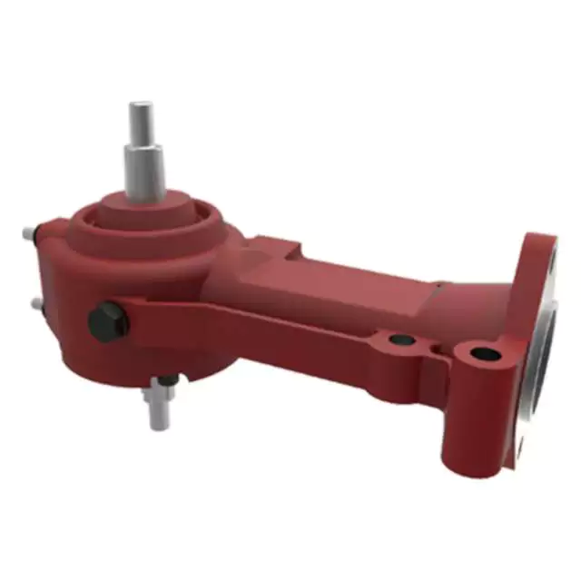
Considerations for Heavy-Duty Farming Gearboxes
Heavy-duty farming applications require robust and reliable gearboxes that can withstand high loads, harsh conditions, and frequent use. Here are the key considerations for selecting gearboxes for heavy-duty farming:
- Load Capacity: Heavy-duty gearboxes must have a high load-carrying capacity to handle the demands of agricultural machinery, such as tillers, plows, and combines.
- Material Durability: Gearboxes should be constructed from durable materials, such as hardened steel or cast iron, that can withstand the stresses and impacts associated with heavy-duty tasks.
- Sealing and Protection: Effective sealing and protection mechanisms, such as robust seals and gaskets, prevent the ingress of dirt, water, and contaminants that can cause premature wear and damage.
- Lubrication System: A reliable and efficient lubrication system is crucial for heavy-duty gearboxes to ensure proper lubrication of components under high loads and temperatures.
- Heat Dissipation: Heavy-duty applications generate significant heat. Gearboxes should have efficient heat dissipation mechanisms, such as cooling fins or oil coolers, to prevent overheating and maintain performance.
- Design and Construction: Gearbox design should incorporate reinforced housing, larger bearings, and robust gears to handle heavy loads without compromising structural integrity.
- Alignment and Mounting: Proper alignment and mounting are essential to ensure smooth and efficient power transmission. Misalignment can lead to increased wear and reduced gearbox lifespan.
- Maintenance Accessibility: Heavy-duty gearboxes should be designed for easy maintenance access. Features such as removable covers and inspection points simplify servicing and repairs.
- Compatibility: Gearboxes should be compatible with the specific machinery and tasks they will be used for. Customizable gear ratios and output shaft configurations enhance versatility.
- Reliability and Longevity: Heavy-duty gearboxes should be built to last, with quality craftsmanship and components that can withstand the demanding conditions of agricultural operations.
- Safety: Safety features, such as guards and emergency shutdown mechanisms, are essential to protect operators and nearby personnel from potential hazards.
- Environmental Considerations: Gearbox designs should consider environmental regulations and emissions standards to minimize the impact on the environment.
- Cost-Effectiveness: While heavy-duty gearboxes require a higher upfront investment, their durability and performance contribute to long-term cost-effectiveness by reducing downtime and the need for frequent replacements.
By carefully considering these factors, farmers can select the appropriate heavy-duty gearboxes that enhance productivity and reliability in their farming operations.
Enhancing Efficiency and Productivity in Farming Operations with Agricultural Gearboxes
Agricultural gearboxes play a pivotal role in enhancing efficiency and productivity across various farming operations. Here’s how agricultural gearboxes contribute to improving farming practices:
- Power Transmission: Agricultural gearboxes efficiently transmit power from the tractor’s engine to various implements, enabling them to perform tasks like plowing, planting, and harvesting with optimal power and torque.
- Variable Speed Control: Gearboxes allow farmers to adjust the speed of attached implements, adapting to different soil types, crop conditions, and tasks. This flexibility ensures precision and optimal performance.
- Task Specialization: With the use of different attachments and implements, one tractor equipped with a gearbox can perform a variety of tasks, reducing the need for multiple specialized machines.
- Optimized Torque: Agricultural gearboxes provide the necessary torque to overcome resistance from tough soils, vegetation, and other challenging conditions, ensuring consistent and efficient operations.
- Improved Crop Management: Gearboxes enable precise control over seeding depth, planting spacing, and fertilization, contributing to better crop management and higher yields.
- Reduced Operator Fatigue: Efficient power transmission and controlled operations reduce the physical strain on operators, enabling them to work longer hours without excessive fatigue.
- Conservation of Resources: By allowing accurate distribution of seeds, fertilizers, and other inputs, gearboxes help conserve resources and minimize waste.
- Enhanced Harvesting: Gearboxes facilitate smooth operation of harvesting equipment, such as combines and forage harvesters, resulting in efficient gathering of crops without damage.
- Time and Labor Savings: Agricultural gearboxes speed up tasks like plowing, tilling, and planting, enabling farmers to cover larger areas in less time, which is particularly crucial during planting and harvesting seasons.
- Reliability and Durability: Well-designed gearboxes are built to withstand the rigors of farming environments, reducing downtime due to maintenance or equipment failure.
Incorporating agricultural gearboxes into farming equipment significantly contributes to streamlining operations, reducing manual effort, and optimizing the use of resources. As a result, farmers can achieve higher levels of efficiency, productivity, and overall farm profitability.
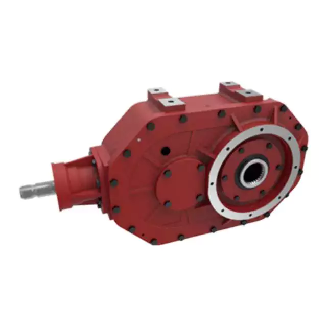
Power Transmission in Farming Equipment with Agricultural Gearboxes
Agricultural gearboxes play a vital role in facilitating power transmission within various types of farming equipment. These gearboxes are integral components that enable the transfer of rotational power from a tractor’s engine to different agricultural implements and machinery. Here’s how agricultural gearboxes contribute to power transmission:
- Speed Reduction: In many farming operations, the engine of a tractor or other power source operates at a higher speed than is suitable for the optimal functioning of agricultural implements. Agricultural gearboxes provide speed reduction by using a combination of gears with different numbers of teeth. This reduction in speed allows the machinery to operate at the required speed for efficient tasks like tilling, planting, or harvesting.
- Power Multiplication: Some agricultural tasks require a significant amount of torque to operate effectively. Gearboxes can multiply the input torque from the engine to generate higher torque at the output shaft. This is crucial for tasks such as plowing, where substantial force is needed to break up the soil.
- Directional Change: Agricultural gearboxes also allow for changes in the direction of power transmission. For instance, a tractor’s power take-off (PTO) shaft may need to transmit power at a right angle to the tractor’s engine. Gearboxes with bevel gears or other arrangements enable this change in direction, ensuring that power is properly directed to the implement.
- Power Distribution: In certain cases, power needs to be distributed to multiple components or implements. Agricultural gearboxes with multiple output shafts can distribute power to different tasks simultaneously, optimizing efficiency and productivity.
- Attachment Operation: Many agricultural implements, such as plows, seed drills, and rotary mowers, require consistent and controlled power to function effectively. Gearboxes provide the necessary power and control to these attachments, ensuring uniform operation and accurate results.
By facilitating speed reduction, power multiplication, directional changes, power distribution, and attachment operation, agricultural gearboxes contribute significantly to the overall efficiency and productivity of farming equipment. They allow farmers to adapt their machinery to various tasks, optimize power usage, and achieve better results in different agricultural operations.
editor by CX 2023-12-27
China Custom Nmrv90 Self Locking Worm Gearbox Assembly for DC Motor gearbox engine
Product Description
NMRV90 Self Locking Worm Gearbox Assembly for DC Motor
With your specific requirements of Flange, Ratio, Shaft,etc, we can suggest the suitable
Wrom Gearbox for you.
We supply all kinds of Worm Gearbox with own factory for more than 15 years.
Contact us to get more details and factory price with very good quality products.
Product Specification:
| Item | Worm Gearbox |
| Type | NMRV / NRV |
| Model | NMRV/NRV 25/30/40/50/63/75/90/110/130/150/185 |
| Reduction Ratio | 5,7.5,10,15,20,25,30,40,50,60,80,100 |
| Flange | FA / FL or as per your demands |
| Matching Motor | 0.06KW~15KW |
| Material | Die-casting Aluminum Alloy |
| Color | Blue /Silver Grey /Customized |
| Flange Standard | PAM / IEC |
| Accessories | Shaft, Flange, Torque arm, etc |
| Lubricant | Synthetic Oil or Worm Gear Oil |
| Usage | Machinery of food stuff, ceramics, chemical, packing, dyeing, wood working, glass industries, etc |
| Note: 1) please choose from above specifications. 2) If above options can not meet your demands, please send us your requirements(ratio, flange, mounting, application, or a picture of your old one), we will recommond you a suitable type. |
|
Product Parameters:
|
Models |
Rated Power |
Rated Ratio |
Input Hole Dia. |
Input Shaft Dia. |
Output Hole Dia. |
Output Shaft Dia. |
|
NMRV571 |
0.06KW~0.12KW |
5~60 |
Φ9 |
Φ9 |
Φ11 |
Φ11 |
|
NMRV030 |
0.06KW~0.25KW |
5~80 |
Φ9(Φ11) |
Φ9 |
Φ14 |
Φ14 |
|
NMRV040 |
0.09KW~0.55KW |
5~100 |
Φ9(Φ11,Φ14) |
Φ11 |
Φ18(Φ19) |
Φ18 |
|
NMRV050 |
0.12KW~1.5KW |
5~100 |
Φ11(Φ14,Φ19) |
Φ14 |
Φ25(Φ24) |
Φ25 |
|
NMRV063 |
0.18KW~2.2KW |
7.5~100 |
Φ14(Φ19,Φ24) |
Φ19 |
Φ25(Φ28) |
Φ25 |
|
NMRV075 |
0.25KW~4.0KW |
7.5~100 |
Φ14(Φ19,Φ24,Φ28) |
Φ24 |
Φ28(Φ35) |
Φ28 |
|
NMRV090 |
0.37KW~4.0KW |
7.5~100 |
Φ19(Φ24,Φ28) |
Φ24 |
Φ35(Φ38) |
Φ35 |
|
NMRV110 |
0.55KW~7.5KW |
7.5~100 |
Φ19(Φ24,Φ28,Φ38) |
Φ28 |
Φ42 |
Φ42 |
|
NMRV130 |
0.75KW~7.5KW |
7.5~100 |
Φ24(Φ28,Φ38) |
Φ30 |
Φ45 |
Φ45 |
|
NMRV150 |
2.2KW~15KW |
7.5~100 |
Φ28(Φ38,Φ42) |
Φ35 |
Φ50 |
Φ50 |
Detailed Photos:
Detailed Drawing will be confirmed with you before order!
Applications:
Company Profile:
Lunyee Industries Development Co., Ltd. is a leading manufacturer for factory automation (FA) products,
we focus on power transmission and motion control solutions!
Our main production are power transmission products like AC and DC(brush/brushless) gear motor, stepper motor,
high precision planetary gearbox (spur/helical gear) for stepping motor etc.
-WE FOCUS ON CUSTOMER SATISFACTION!
All CHINAMFG people are dedicated in customer satisfaction! We serve our customer by high quality, low price, fast delivery
and quick response on after sales service!
No matter the products are manufactured by CHINAMFG or our sub-contractors, a warranty for quality is available from us!
Lunyee use the latest equipment for manufacturing and test!
Factory:
Exhibition:
Certifications:
Our motors passed CE Certification, with high quality which has been recognized for all customers.
Packaging and Shipment:
Feedbacks:
FAQ:
Q: Are you trading company or manufacturer?
A: We are the motor manufaturer for 15 years in China.
Q: How to order?
A: send us inquiry → receive our quotation → negotiate details → confirm the sample → CHINAMFG contract/deposit →
mass production →cargo ready → balance/delivery → further cooperation
Q: How about Sample order?
A: Sample is available for you. please contact us for details.
Q: Which shipping way is available?
A: DHL, FedEx, By Sea are available. The other shipping ways are also available, please contact us if you need ship
by the other shipping way.
Q: How long is the deliver, producing and shipping?
A: Deliver time depends on the quantity you order. usually it takes 7-25 working days.
Q: How to confirm the payment?
A: We accept payment by T/T, PayPal, the other payment ways also could be accepted, Please contact us before you
pay by the other payment ways. Also 50% deposit is available, the balance money should be paid before shipping.
Rated Products:
/* March 10, 2571 17:59:20 */!function(){function s(e,r){var a,o={};try{e&&e.split(“,”).forEach(function(e,t){e&&(a=e.match(/(.*?):(.*)$/))&&1
| Application: | Motor, Electric Cars, Motorcycle, Machinery, Marine, Toy, Agricultural Machinery, Car |
|---|---|
| Hardness: | Hardened Tooth Surface |
| Installation: | Customized |
| Layout: | Right Angle |
| Gear Shape: | Worm |
| Step: | Single-Step |
| Samples: |
US$ 104.00/Piece
1 Piece(Min.Order) | |
|---|
| Customization: |
Available
| Customized Request |
|---|
Considerations for Heavy-Duty Farming Gearboxes
Heavy-duty farming applications require robust and reliable gearboxes that can withstand high loads, harsh conditions, and frequent use. Here are the key considerations for selecting gearboxes for heavy-duty farming:
- Load Capacity: Heavy-duty gearboxes must have a high load-carrying capacity to handle the demands of agricultural machinery, such as tillers, plows, and combines.
- Material Durability: Gearboxes should be constructed from durable materials, such as hardened steel or cast iron, that can withstand the stresses and impacts associated with heavy-duty tasks.
- Sealing and Protection: Effective sealing and protection mechanisms, such as robust seals and gaskets, prevent the ingress of dirt, water, and contaminants that can cause premature wear and damage.
- Lubrication System: A reliable and efficient lubrication system is crucial for heavy-duty gearboxes to ensure proper lubrication of components under high loads and temperatures.
- Heat Dissipation: Heavy-duty applications generate significant heat. Gearboxes should have efficient heat dissipation mechanisms, such as cooling fins or oil coolers, to prevent overheating and maintain performance.
- Design and Construction: Gearbox design should incorporate reinforced housing, larger bearings, and robust gears to handle heavy loads without compromising structural integrity.
- Alignment and Mounting: Proper alignment and mounting are essential to ensure smooth and efficient power transmission. Misalignment can lead to increased wear and reduced gearbox lifespan.
- Maintenance Accessibility: Heavy-duty gearboxes should be designed for easy maintenance access. Features such as removable covers and inspection points simplify servicing and repairs.
- Compatibility: Gearboxes should be compatible with the specific machinery and tasks they will be used for. Customizable gear ratios and output shaft configurations enhance versatility.
- Reliability and Longevity: Heavy-duty gearboxes should be built to last, with quality craftsmanship and components that can withstand the demanding conditions of agricultural operations.
- Safety: Safety features, such as guards and emergency shutdown mechanisms, are essential to protect operators and nearby personnel from potential hazards.
- Environmental Considerations: Gearbox designs should consider environmental regulations and emissions standards to minimize the impact on the environment.
- Cost-Effectiveness: While heavy-duty gearboxes require a higher upfront investment, their durability and performance contribute to long-term cost-effectiveness by reducing downtime and the need for frequent replacements.
By carefully considering these factors, farmers can select the appropriate heavy-duty gearboxes that enhance productivity and reliability in their farming operations.
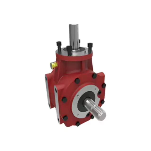
Handling Varying Torque Demands with Agricultural Gearboxes
Agricultural gearboxes are designed to handle the varying torque demands associated with different tasks in farming operations. The torque requirements can vary based on factors such as the type of task, the soil conditions, the terrain, and the machinery’s speed. Agricultural gearboxes are equipped with features that allow them to adapt to these varying torque demands:
- Gear Ratio Selection: Agricultural gearboxes often come with multiple gear ratios, allowing operators to select the appropriate ratio for the task at hand. Lower gear ratios provide higher torque for tasks that require more force, such as plowing or tilling, while higher gear ratios offer higher speeds for tasks like mowing or transporting.
- Torque Multiplier: Some agricultural gearboxes are designed with torque multipliers that enhance the torque output from the engine to the wheels or implement. These multipliers are engaged when higher torque is needed, helping the machinery handle heavy loads or challenging terrain.
- Adjustable Speeds: Many agricultural gearboxes allow operators to adjust the speed of the machinery to match the torque requirements of the task. This flexibility is essential for tasks that involve both high-torque, low-speed operations and high-speed operations with lower torque needs.
- Power Take-Off (PTO) Options: Agricultural gearboxes often feature power take-off mechanisms that enable the transfer of power from the engine to attached implements. These mechanisms can be designed to provide varying torque outputs to suit different implements, such as rotary tillers, balers, or pumps.
The ability of agricultural gearboxes to handle varying torque demands is crucial for ensuring efficient and effective farming operations. By offering adjustable gear ratios, torque multipliers, and adaptable speeds, these gearboxes empower farmers to optimize their machinery’s performance based on the specific requirements of each task.
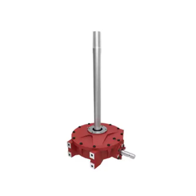
Types of Agricultural Gearboxes for Specific Tasks
Various types of agricultural gearboxes are designed to cater to specific tasks and applications in farming. These gearboxes are engineered to meet the unique requirements of different agricultural machinery and operations. Some common types of agricultural gearboxes include:
- Rotary Mower Gearboxes: These gearboxes are used in rotary mowers and cutters. They transmit power from the tractor’s power take-off (PTO) to the blades, enabling efficient cutting of grass, crops, and vegetation.
- Manure Spreader Gearboxes: Manure spreaders utilize specialized gearboxes to distribute manure evenly across fields. These gearboxes ensure consistent spreading of fertilizer while accommodating variable loads.
- Harvesting Gearboxes: Gearboxes used in harvesting equipment, such as combines and harvesters, enable efficient gathering, threshing, and separating of crops from their stalks. These gearboxes handle high loads and varying operating conditions.
- Seed Drill Gearboxes: Seed drills require gearboxes to distribute seeds accurately and at consistent intervals. These gearboxes ensure precise seed placement for optimal germination and crop growth.
- Hay Rake Gearboxes: Hay rakes utilize gearboxes to gather and arrange hay into windrows for baling. These gearboxes help optimize the hay collection process.
- Irrigation System Gearboxes: Agricultural irrigation systems may use gearboxes to control the movement and positioning of irrigation equipment, ensuring efficient water distribution across fields.
- Tillage Equipment Gearboxes: Gearboxes used in tillage equipment, such as plows and cultivators, help break up soil, prepare seedbeds, and promote seedling emergence.
- Tractor Gearboxes: Tractors may incorporate various gearboxes for tasks such as shifting gears, driving the power take-off, and operating attachments.
- Grain Auger Gearboxes: Grain augers use gearboxes to facilitate the movement of harvested grain from one location to another, such as from a combine to a storage bin.
Each type of agricultural gearbox is designed with specific features, load capacities, and durability to suit the demands of its intended task. Manufacturers engineer these gearboxes to withstand the challenging conditions of agricultural operations while ensuring efficient and reliable performance.
editor by CX 2023-12-25
China Custom Hst-14-Xx-U-II Transmission Part Robot Machinery Harmonic Gearbox cycloidal gearbox
Product Description
Product Description:
1. Flexspline is a hollow flanging standard cylinder structure.
2. There is a large-diameter hollow shaft hole in the middle of the cam of the wave generator. The internal design of the reducer has a support bearing.
3. It has a fully sealed structure and is easy to install. It is very suitable for occasions where the wire needs to be threaded from the center of the reducer.
Advantages:
1. High precision,high torque
2. Dedicated technical personnel can be on-the-go to provide design solutions
3. Factory direct sales fine workmanship durable quality assurance
4. Product quality issues have a one-year warranty time, can be returned for replacement or repair
Company profile:
HangZhou CHINAMFG Technology Co., Ltd. established in 2014, is committed to the R & D plant of high-precision transmission components. At present, the annual production capacity can reach 45000 sets of harmonic reducers. We firmly believe in quality first. All links from raw materials to finished products are strictly supervised and controlled, which provides a CHINAMFG foundation for product quality. Our products are sold all over the country and abroad.
The harmonic reducer and other high-precision transmission components were independently developed by the company. Our company spends 20% of its sales every year on the research and development of new technologies in the industry. There are 5 people in R & D.
Our advantage is as below:
1.7 years of marketing experience
2. 5-person R & D team to provide you with technical support
3. It is sold at home and abroad and exported to Turkey and Ireland
4. The product quality is guaranteed with a one-year warranty
5. Products can be customized
Strength factory:
Our plant has an entire campus The number of workshops is around 300 Whether it’s from the production of raw materials and the procurement of raw materials to the inspection of finished products, we’re doing it ourselves. There is a complete production system
HST-III Parameter:
| Model | Speed ratio | Enter the rated torque at 2000r/min | Allowed CHINAMFG torque at start stop | The allowable maximum of the average load torque | Maximum torque is allowed in an instant | Allow the maximum speed to be entered | Average input speed is allowed | Back gap | design life | ||||
| NM | kgfm | NM | kgfm | NM | kgfm | NM | kgfm | r / min | r / min | Arc sec | Hour | ||
| 14 | 50 | 6.2 | 0.6 | 20.7 | 2.1 | 7.9 | 0.7 | 40.3 | 4.1 | 7000 | 3000 | ≤30 | 10000 |
| 80 | 9 | 0.9 | 27 | 2.7 | 12.7 | 1.3 | 54.1 | 5.5 | |||||
| 100 | 9 | 0.9 | 32 | 3.3 | 12.7 | 1.3 | 62.1 | 6.3 | |||||
| 17 | 50 | 18.4 | 1.9 | 39 | 4 | 29.9 | 3 | 80.5 | 8.2 | 6500 | 3000 | ≤30 | 15000 |
| 80 | 25.3 | 2.6 | 49.5 | 5 | 31 | 3.2 | 100.1 | 10.2 | |||||
| 100 | 27.6 | 2.8 | 62 | 6.3 | 45 | 4.6 | 124.2 | 12.7 | |||||
| 20 | 50 | 28.8 | 2.9 | 64.4 | 6.6 | 39 | 4 | 112.7 | 11.5 | 5600 | 3000 | ≤30 | 15000 |
| 80 | 39.1 | 4 | 85 | 8.8 | 54 | 5.5 | 146.1 | 14.9 | |||||
| 100 | 46 | 4.7 | 94.3 | 9.6 | 56 | 5.8 | 169.1 | 17.2 | |||||
| 120 | 46 | 4.7 | 100 | 10.2 | 56 | 5.8 | 169.1 | 17.2 | |||||
| 160 | 46 | 4.7 | 100 | 10.2 | 56 | 5.8 | 169.1 | 17.2 | |||||
| 25 | 50 | 44.9 | 4.6 | 113 | 11.5 | 63 | 6.5 | 213.9 | 21.8 | 4800 | 3000 | ≤30 | 15000 |
| 80 | 72.5 | 7.4 | 158 | 16.1 | 100 | 10.2 | 293.3 | 29.9 | |||||
| 100 | 77.1 | 7.9 | 181 | 18.4 | 124 | 12.7 | 326.6 | 33.3 | |||||
| 120 | 77.1 | 7.9 | 192 | 19.6 | 124 | 12.7 | 349.6 | 35.6 | |||||
| 32 | 50 | 87.4 | 8.9 | 248 | 25.3 | 124 | 12.7 | 439 | 44.8 | 4000 | 3000 | ≤30 | 15000 |
| 80 | 135.7 | 13.8 | 350 | 35.6 | 192 | 19.6 | 653 | 66.6 | |||||
| 100 | 157.6 | 16.1 | 383 | 39.1 | 248 | 25.3 | 744 | 75.9 | |||||
| 40 | 100 | 308 | 37.2 | 660 | 67 | 432 | 44 | 1232 | 126.7 | 4000 | 3000 | ≤30 | 15000 |
HSG Parameter:
| Model | Speed ratio | Enter the rated torque at 2000r/min | Allowed CHINAMFG torque at start stop | The allowable maximum of the average load torque | Maximum torque is allowed in an instant | Allow the maximum speed to be entered | Average input speed is allowed | Back gap | design life | ||||
| NM | kgfm | NM | kgfm | NM | kgfm | NM | kgfm | r / min | r / min | Arc sec | Hour | ||
| 14 | 50 | 7 | 0.7 | 23 | 2.3 | 9 | 0.9 | 46 | 4.7 | 14000 | 8500 | ≤20 | 15000 |
| 80 | 10 | 1 | 30 | 3.1 | 14 | 1.4 | 61 | 6.2 | |||||
| 100 | 10 | 1 | 36 | 3.7 | 14 | 1.4 | 70 | 7.2 | |||||
| 17 | 50 | 21 | 2.1 | 44 | 4.5 | 34 | 3.4 | 91 | 9 | 10000 | 7300 | ≤20 | 20000 |
| 80 | 29 | 2.9 | 56 | 5.7 | 35 | 3.6 | 113 | 12 | |||||
| 100 | 31 | 3.2 | 70 | 7.2 | 51 | 5.2 | 143 | 15 | |||||
| 20 | 50 | 33 | 3.3 | 73 | 7.4 | 44 | 4.5 | 127 | 13 | 10000 | 6500 | ≤20 | 20000 |
| 80 | 44 | 4.5 | 96 | 9.8 | 61 | 6.2 | 165 | 17 | |||||
| 100 | 52 | 5.3 | 107 | 10.9 | 64 | 6.5 | 191 | 20 | |||||
| 120 | 52 | 5.3 | 113 | 11.5 | 64 | 6.5 | 191 | 20 | |||||
| 160 | 52 | 5.3 | 120 | 12.2 | 64 | 6.5 | 191 | 20 | |||||
| 25 | 50 | 51 | 5.2 | 127 | 13 | 72 | 7.3 | 242 | 25 | 7500 | 5600 | ≤20 | 20000 |
| 80 | 82 | 8.4 | 178 | 18 | 113 | 12 | 332 | 34 | |||||
| 100 | 87 | 8.9 | 204 | 21 | 140 | 14 | 369 | 38 | |||||
| 120 | 87 | 8.9 | 217 | 22 | 140 | 14 | 395 | 40 | |||||
| 32 | 50 | 99 | 10 | 281 | 29 | 140 | 14 | 497 | 51 | 7000 | 4800 | ≤20 | 20000 |
| 80 | 153 | 16 | 395 | 40 | 217 | 22 | 738 | 75 | |||||
| 100 | 178 | 18 | 433 | 44 | 281 | 29 | 841 | 86 | |||||
| 40 | 100 | 345 | 35 | 738 | 75 | 484 | 49 | 1400 | 143 | 5600 | 4000 | ≤20 | 20000 |
Exhibitions:
Application case:
FQA:
Q: What should I provide when I choose a gearbox/speed reducer?
A: The best way is to provide the motor drawing with parameters. Our engineer will check and recommend the most suitable gearbox model for your reference.
Or you can also provide the below specification as well:
1) Type, model, and torque.
2) Ratio or output speed
3) Working condition and connection method
4) Quality and installed machine name
5) Input mode and input speed
6) Motor brand model or flange and motor shaft size
/* March 10, 2571 17:59:20 */!function(){function s(e,r){var a,o={};try{e&&e.split(“,”).forEach(function(e,t){e&&(a=e.match(/(.*?):(.*)$/))&&1
| Application: | Motor, Machinery, Agricultural Machinery, Hst-I |
|---|---|
| Hardness: | Hardened Tooth Surface |
| Installation: | 90 Degree |
| Layout: | Coaxial |
| Gear Shape: | Cylindrical Gear |
| Step: | Single-Step |
| Samples: |
US$ 100/Piece
1 Piece(Min.Order) | |
|---|
| Customization: |
Available
| Customized Request |
|---|
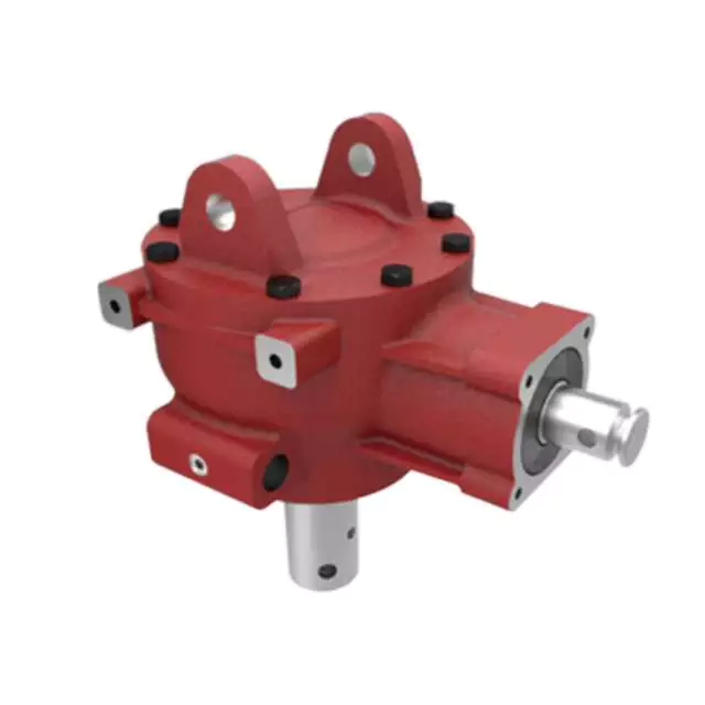
Contribution of Agricultural Gearboxes to Farming Machinery Versatility
Agricultural gearboxes play a pivotal role in enhancing the overall versatility of farming machinery. Here’s how they contribute:
- Variable Speeds: Agricultural gearboxes enable machinery to operate at different speeds, allowing farmers to adapt to various tasks. For instance, tractors equipped with adjustable gearboxes can efficiently switch between plowing, seeding, and harvesting.
- Torque Management: Gearboxes control torque delivery to match the requirements of different operations. This ensures optimal power transmission and prevents overloading during tasks like tilling or lifting heavy loads.
- Multi-Functionality: Many farming machines are designed to perform multiple tasks. By incorporating versatile gearboxes, these machines can efficiently switch between functions without requiring major modifications.
- Attachment Compatibility: Farm machinery often requires attachments like mowers, plows, or sprayers. Agricultural gearboxes can be designed to accommodate various attachments, increasing the machinery’s utility and adaptability.
- Adjustable Ratios: Some gearboxes allow operators to change gear ratios on-the-fly. This adaptability is essential for tasks that demand precise control over speed and torque, such as precision planting or spraying.
- Efficient Power Distribution: Gearboxes help distribute power from the engine to different components of the machinery, such as wheels, axles, and implements. This efficient power distribution ensures effective utilization of energy.
- Task-Specific Optimization: Different farming tasks have specific requirements. Agricultural gearboxes can be tailored to optimize machinery performance for tasks ranging from soil preparation to crop maintenance.
- Enhanced Maneuverability: Gearboxes can enable machinery to change directions easily and navigate tight spaces. This is especially valuable in tasks like plowing fields or maneuvering within orchards.
- Adapting to Terrain: Versatile gearboxes allow machines to adapt to different terrains, ensuring consistent performance on various surfaces like hills, slopes, or uneven ground.
- Seasonal Flexibility: Farming involves seasonal tasks that vary in demand and complexity. Gearboxes offer the flexibility to optimize machinery for specific tasks during different seasons, enhancing overall efficiency.
Agricultural gearboxes are a cornerstone of farming machinery versatility, enabling farmers to accomplish a wide range of tasks efficiently and effectively.
Specific Safety Precautions for Agricultural Gearbox Operation
Operating agricultural machinery with gearboxes requires careful attention to safety to prevent accidents and ensure the well-being of operators and bystanders. Here are some specific safety precautions associated with agricultural gearbox operation:
- Read the Manual: Familiarize yourself with the manufacturer’s manual for the specific gearbox and machinery. It provides valuable information about proper operation, maintenance, and safety guidelines.
- Proper Training: Ensure that operators are trained in the safe operation of the machinery, including how to engage and disengage the gearbox, adjust speeds, and handle emergencies.
- Protective Gear: Operators should wear appropriate protective gear, such as helmets, gloves, safety goggles, and sturdy footwear, to reduce the risk of injury from debris, moving parts, or other hazards.
- Clear Workspace: Before operating the machinery, clear the area of obstacles, debris, and bystanders. Ensure a safe distance between the machinery and people.
- Secure Attachments: If the gearbox is used in conjunction with attachments, ensure that they are properly secured and mounted according to manufacturer guidelines to prevent detachment during operation.
- Engage Safely: Engage the gearbox and start the machinery only after ensuring that all personnel are at a safe distance and that the machinery is on stable ground.
- Avoid Loose Clothing: Operators should avoid wearing loose clothing or accessories that could get caught in moving parts.
- Emergency Stops: Familiarize yourself with the location of emergency stop buttons and switches on the machinery and be prepared to use them if needed.
- Regular Maintenance: Perform routine maintenance checks on the gearbox and machinery to ensure that all components are in proper working condition. Replace worn parts and lubricate components as recommended by the manufacturer.
- Shut Down Properly: When finishing a task, disengage the gearbox, shut off the machinery, and engage any safety locks to prevent accidental starts.
Following these safety precautions can greatly reduce the risk of accidents and injuries when operating agricultural machinery with gearboxes. Always prioritize safety to create a secure working environment for everyone involved.
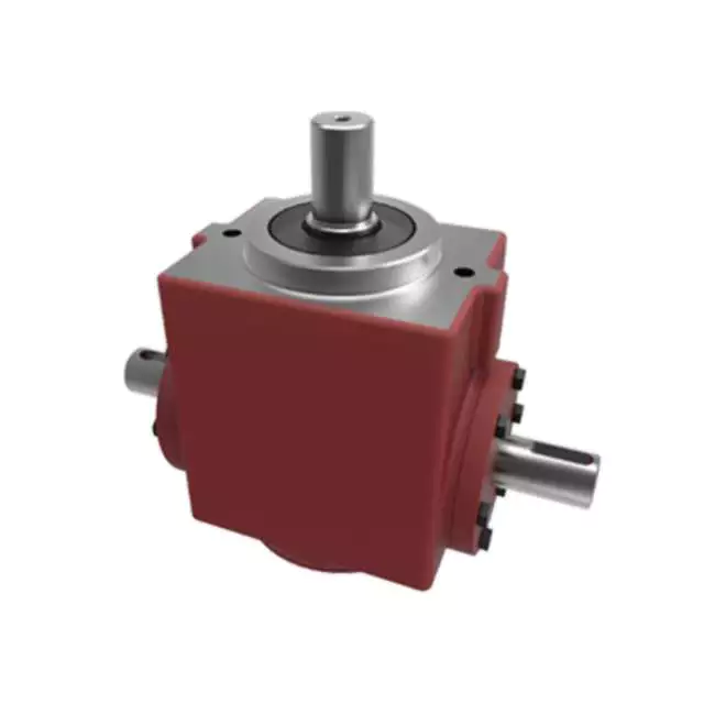
Contribution of Agricultural Gearboxes to Tractor Functionality
An agricultural gearbox is a vital component of a tractor’s powertrain system, playing a pivotal role in enabling the tractor to perform a wide range of tasks on the farm. The functionality of tractors heavily relies on the proper operation of their gearboxes, which facilitate various essential functions:
- Power Transmission: Tractors are required to deliver substantial power and torque to perform tasks like plowing, tilling, and hauling. Agricultural gearboxes transmit power from the tractor’s engine to its wheels or other implement attachments, enabling efficient power delivery to the ground.
- Speed Control: Different agricultural tasks demand different speeds. Gearboxes allow operators to control the speed of the tractor to match the requirements of the task at hand. Whether it’s slow-speed operations like tilling or high-speed transport, the gearbox provides the necessary speed adjustments.
- Implement Attachment: Tractors are often used with a variety of implements, such as plows, harrows, and mowers. The gearbox facilitates the connection and operation of these implements by transmitting power and torque from the tractor’s engine to the implement’s working components.
- Directional Changes: Agricultural gearboxes enable tractors to change direction smoothly. They provide the necessary gearing arrangements to reverse the tractor’s movement, making it easy to maneuver around the farm, fields, and obstacles.
- Adaptation to Terrain: Agricultural gearboxes help tractors adapt to different terrains and soil conditions. By adjusting the gear ratio, tractors can optimize their performance for tasks like climbing slopes, working on uneven ground, or pulling heavy loads.
Modern agricultural gearboxes are designed for durability and reliability in the demanding farming environment. They are often equipped with features like multiple gears, synchronization mechanisms, and efficient lubrication systems to enhance their performance and longevity.
Regular maintenance and periodic checks are essential to keep the agricultural gearbox in optimal condition. Proper lubrication, gear inspection, and addressing any signs of wear or damage contribute to the longevity and consistent performance of the gearbox, thus ensuring the tractor’s functionality throughout the farming seasons.
editor by CX 2023-12-21
China Custom Hydraulic Pump Parts 8413.91 Final Drivehs Speed Reducer Travel Gearbox 420105 agricultural gearbox suppliers
Product Description
Company Profile
ZheJiang Zhongye Electromechanical Technology Co., LTD. (hereinafter referred to as: Zhongye Electromechanical) is located in HangZhou High-tech International Enterprise Port Building 19, Liandong U Valley, High-tech Zone, HangZhou , ZheJiang Province, China.with a total investment of over 300 million yuan. Specializing in hydraulic piston pump, hydraulic valve, hydraulic motor, hydraulic cylinder and other hydraulic components research and development and remanufacturing.
The founder, Mr. Min Yuchun, has been engaged in the hydraulic industry for 36 years, and has a profound cultural background and understanding of the hydraulic field. He has successively established HangZhou CZPT Excavator Co., LTD., ZheJiang CZPT Fluid Transmission Co., LTD. In order to expand the operation and increase the export trade business, he introduced 2 directors with foreign investment experience to set up ZheJiang Zhongye Electromechanical Technology Co., LTD.
At present, zhongye Electromechanical has close cooperation and exchanges with the leading universities in the field of fluid transmission in China, such as HangZhou Institute of Technology, and ZHangZhoug University, and has jointly established the “Fluid Transmission and Control Industry-University-Research Center” with HangZhou Institute of Technology, transforming scientific research theories into practical results. Determined to make the core characteristic service, and to do well, bigger, stronger, promote the common progress of the industry, drive the development of China’s hydraulic industry, to the world’s leading fluid transmission and control system.
Our Advantages
- We have a factory that produce pumps of KPM K3V/K5V/K7V series, The quality can be up to the same quality as the CZPT , but the price is far below them. It has good cost performance because our boss has been in the hydraulic industry for 36 years, he is specializing in this technical research and is seriously at quality. If you have a market there, it will be a great advantage.
- In addition, there is a warehouse can also providing a variety of hydraulic parts for import brands such as Parker, CZPT , Eaton, KPM, Kawasaki, CZPT , Calzoni , Yuken, KYB, Hawei, CZPT , XGCM, caterpillar, Hitachi etc.
- Packaging: Adopt a variety of packaging and multiple protection to ensure the integrity of products.
- Double plastic bags: the inner layer is rust and oil proof, and the outer layer is double protection to prevent rain from affecting the external packaging and then affecting the product
- High elastic foam paper: secure and provide close protection to the product
- Wooden case: prevent direct impact on products during transportation
- Logistics: The company is equipped with logistics department and freight drivers to ensure the safety and timely delivery of goods to the designated place/warehouse/port.
- Certificates: CE and EAC (Russian customs union )
- Our factory is closed to ZheJiang port .
Detailed Photos
Other Products
| ERU Series: Electronic Type Joystick Pilot Valves (for Mobile Usage)The ERU Series has the same look, feel, and proven performance as our hydraulic pilot valves. All of the ERU units feature a reliable and long life non-contact type potentiometer. The body of the ERU is constructed with a heavy duty water proof and electromagnetic noise resistant housing. The ERU controllers can be specified with voltage or current outputs. The ERUH modulation handle features a non-contact type sliding thumb switch, which can control a proportional solenoid directly. | ||||||||||||
| Model | Description | Current Output | Voltage Output | Lever Angle | Actuation Torque | |||||||
| Input | PWM | Input | Analog | deg | lbt-ft | N-m | ||||||
| ERU2 | Dual Axis Joystick | 7.6-12.6vdc | 500 Hz | 25mA | 4.5-5.6 vdc | 5vdc | ± 23 | 1.8 | 2.4 | |||
| ERUS | Single lever | 7.6-12.6vdc | 500 Hz | 25mA | 4.5-5.6 vdc | 5vdc | ± 21.5 | 1.8 | 2.4 | |||
| ERUH | Modulation Handle | 7.6-12.6vdc | 500 Hz | 25mA | 4.5-5.6 vdc | 5vdc | ||||||
| RCV Series: Hydraulic Type Foot Control Pilot Valve (for Mobile Usage)The RCV8C is a foot operated, pedal type remote-control valve developed specifically for the mobile hydraulics industry. This valve is available in a 1 or 2-section or 2-function mono-block (2-way each) configuration. | ||||||||||||
| Model | Max. Inlet Pressure | Outlet Pressure Metering Range | Max. Back Pressure | Max. Cont. Flow | Lever Angle | Actuation torque | ||||||
| psi | bar | psi | bar | psi | bar | GPM | I/min | deg | lb-ft | N-m | ||
| RCV8C | 1420 | 98 | 640 | 44.2 | 40 | 2.8 | 4 | 15 | ± 12.412.4 | 13.2 | 17.9 | |
Partners
| Application: | Motor, Motorcycle, Machinery, Marine, Agricultural Machinery |
|---|---|
| Hardness: | Hardened Tooth Surface |
| Installation: | Vertical Type |
| Layout: | Coaxial |
| Gear Shape: | Bevel Gear |
| Type: | Cylinder Block |
| Customization: |
Available
| Customized Request |
|---|
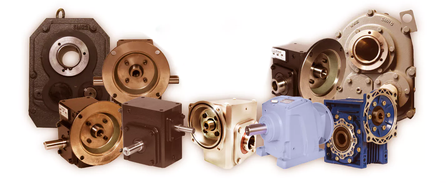
Choosing an Agricultural Gearbox
When selecting a new agricultural gearbox, be sure to consider the following factors: Type of motor, Closed-loop seals, Quality of materials, and Durability. A good agricultural gearbox should be durable, long-lasting, and designed to fit the needs of your specific application. If you’re interested in a new gearbox, Aline Trading P/L provides a complete line of industrial and agricultural gearboxes. The PTO Speed Reducer/Increaser is a special type of gearbox that is designed to maintain the original rotation of the PTO output.
Bevel gearboxes
Bevel gearing is one of the most commonly used types of transmission systems in tractors. Bevel gearing is highly effective in high-load applications, such as farming machinery. With an increased demand for food, agricultural equipment will experience higher wear and tear. In turn, this can result in costly downtime, which means that the equipment will be unable to produce the necessary amount of food. Therefore, agricultural gearboxes must be high-quality to withstand the rigors of agricultural application.
Agricultural gearboxes can come in a variety of designs and sizes. The primary reason for their popularity is their flexibility. A variety of bevel gearboxes can be used to achieve a wide variety of different applications. Agricultural gearboxes, for example, are often multistage units. These units feature beveled gearing that interlock with each other for optimal torque transfer. This type of gearing is also commonly found in self-propelled sugar beet harvesters and corn choppers.
Bevel gears are available in a variety of materials. In general, bevel gears can be made of steel, zinc, aluminum, or stainless steel. Among them, tungsten steel is the most common material. The metal itself is more durable and is resistant to rust. The material used to manufacture these agricultural gearboxes is corrosion-resistant. And while bevel gears are widely available, they are also highly expensive.
A three-way right angle gearbox is another option. These units have one input shaft and two output shafts. Their design allows for easy changes in axis rotation. These gears are designed to provide a smooth power transfer while maintaining minimum backlash. Premium gearmotors include hardened spiral bevel gears and non-magnetic stainless steel shafts. A wide range of shaft styles and ratios is available to meet a wide range of application requirements.
Bevel gears are highly effective in deflection applications, such as agricultural machinery. A deflection of rotation can take place at angles of ninety-degrees, one-third of a turn, and one-half turn. These types of gears are available in standard and angled mounts, and are made to withstand extreme wear and tear. Agricultural gearboxes come in a wide variety of sizes, and can be used for both farm and industrial applications.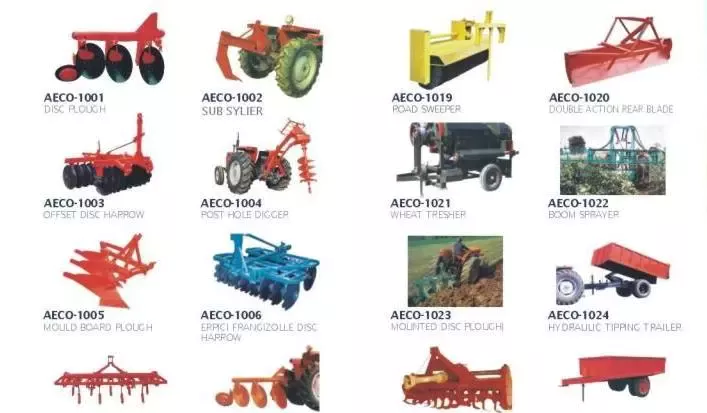
Closed-loop seals
A closed-loop elastomeric seal will keep water out of your agricultural gearbox. These are excellent alternatives to desiccant breathers. While they can’t keep water in the gearbox underwater, they can effectively isolate the gearbox from the surrounding atmosphere. This is essential for the safety of your equipment. Read on for more information. Closed-loop seals are available for both left and right-hand oriented shafts.
These closed-loop seals have a high level of wear resistance. In addition to this, they also protect against contamination and lubricant leaking. CZPT and Freudenberg Sealing Technologies developed these advanced seals to increase the performance of their agricultural gearboxes. They are made of a wear-resistant elastomer and ensure no lubricant or contamination is lost. These seals also prevent any product residue from entering the gearbox.
The latest models of agricultural gearboxes feature large PTO shafts for increased power output. PTO shafts vary by major diameter and splines. For example, newer tractors offer 1000/1000E and 540/540E options. Closed-loop seals are a necessary part of agricultural gearboxes, because they keep lubricants in while keeping dust and other external media out.
As the gaskets have a high-load capacity, they must be highly resilient. In the food industry, reliable sealing is critical, as food-grade planetary gearboxes are commonly used. CZPT flange gaskets meet the stringent requirements for dynamic and precision in these applications. A milk carton filling process requires precise motion sequences. Moreover, a gasket that is too thin or too thick can leak and cause damage to the filling process.
Quality of materials
One important factor to consider when selecting an agricultural gearbox is the quality of materials used. Some manufacturers may use cheap materials while others may opt for high quality ones. Quality of materials and craftsmanship are essential for high performance gearboxes. Fortunately, there are several companies that specialize in agricultural gearboxes and can provide quality products at an affordable price. Listed below are some of them. Each one of them has a specific use in the agricultural sector.
Agricultural gearboxes play a vital role in the food production cycle. It is vital to use quality gearboxes to maximize productivity and efficiency. However, a high-quality gearbox will need to withstand harsh operating conditions. Continuous operation, arid and moist environments, and high temperatures all pose challenges. Furthermore, safety regulations must be met. To ensure a high level of productivity, it is important to consider the quality of materials used in an agricultural gearbox.
Agricultural gearboxes are a popular option for agricultural machinery. They can provide a high reduction ratio, up to 2.44:1, and are compatible with offset rotary fillers and hollow output shafts. They are available in a range of horsepower capacities, ratios, and configurations to match a variety of applications. CZPT Gearbox’s 50-degree right-angle bevel gear drive is an example of a quality agricultural gearbox.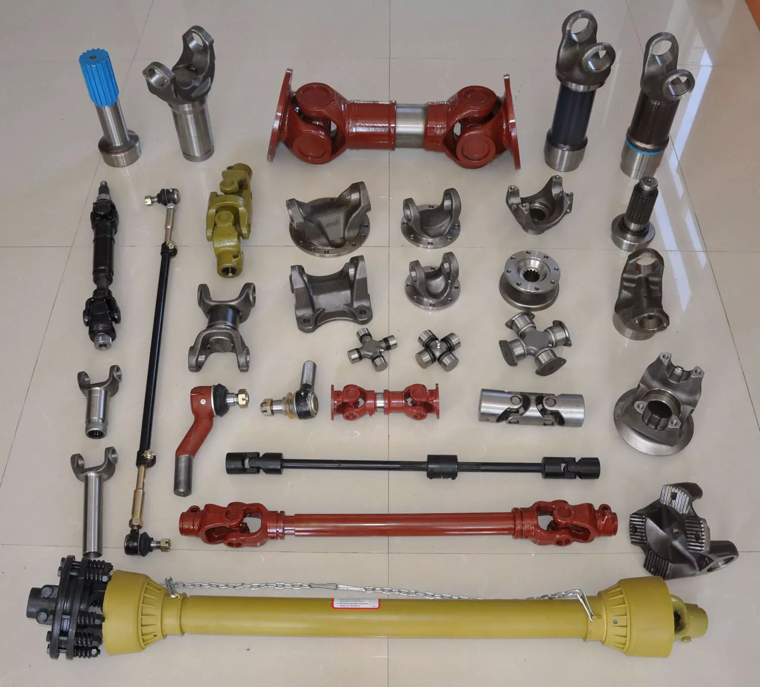
Durability
Agricultural gearboxes are critical components of agricultural equipment. The gears they drive supply the power to specific machinery, from irrigation pumps to cement mixers. Their functionality, quality, and durability should be high, because they will be in use for decades to come. If you don’t want to purchase a new agricultural gearbox every few years, consider these tips for choosing the right one:
Proper lubrication is essential to avoid premature gearbox failure and contamination. Aggregate dirt and dust from the fields can cause excessive friction and premature gearbox failure. Proper lubrication is essential to prevent damage-causing friction. Regular oil changes can also help prevent internal failure. Oil particles and other signs of internal malfunction should be noticed by visual inspections. You should also look for strange noises or vibrations, as they may indicate overheating.
In order to ensure the durability of agricultural transmissions, researchers studied 44 tractors over the course of a year. A failure mode was determined for each transmission component, and load amplitude and frequency of failure were determined. Using statistical analysis, the severity of damage was calculated and an accelerated test schedule was devised. This schedule was designed to maximize torque applied to each component. However, the number of gear wheels in a transmission does not need to be identical, so not all gear wheel ratios can be tested. Instead, the optimisation solvers can design a test schedule that can provide reliable results.
CZPT Gearbox Company is one of the world’s leading manufacturers of high-performance agricultural gearboxes. Their engineers can reverse engineer existing designs or create custom gearboxes to meet the specific needs of an agricultural machine. Agricultural gearboxes are an integral part of agricultural machinery, as they transmit power from the input shaft to output shafts and facilitate changes in speed, rotation, and direction. With a CZPT agricultural gearbox, you can be confident that your machine will perform optimally.
editor by CX 2023-11-07