Tag Archives: tractor agricultural machinery farm

China Right Angle Gear Box Pto Farm Rotary Slasher Feeder Mixer Rotary Tiller Cultivator Baller Tractor Agricultural Machinery Parts Bevel Gearbox agricultural gearboxes

Item Description

Solution Description

Organization Profile

In 2571, HangZhou CZPT Machinery Co.,ltd was set up by Ms. Iris and her 2 associates(Mr. Tian and Mr. Yang) in HangZhou town(ZHangZhoug province, China), all 3 Founders are engineers who have more than averaged 30 a long time of expertise. Then because the requirements of business expansion, in 2014, it moved to the present Xihu (West Lake) Dis. Industrial Zone (HangZhou town, ZHangZhoug province, China).

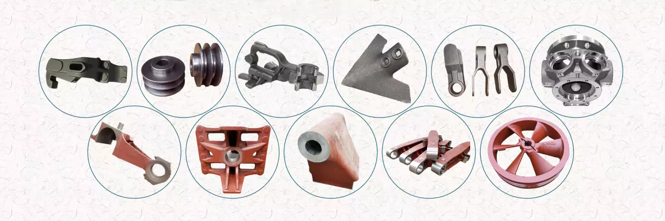
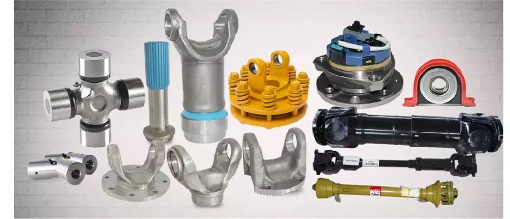
Through our effectively-known brand ND, CZPT Machinery provides agricultural answers to agriculture machinery producer and distributors around the world by means of a entire line of spiral bevel gearboxes, straight bevel gearboxes, spur gearboxes, drive shafts, sheet steel, hydraulic cylinder, motors, tyre, worm gearboxes, worm operators etc. Goods can be customized as request.

We, CZPT equipment set up a total top quality management technique and sales services community to offer customers with substantial-top quality items and satisfactory support. Our goods are marketed in forty provinces and municipalities in China and 36 countries and regions in the planet, our principal industry is the European market place.

Certifications

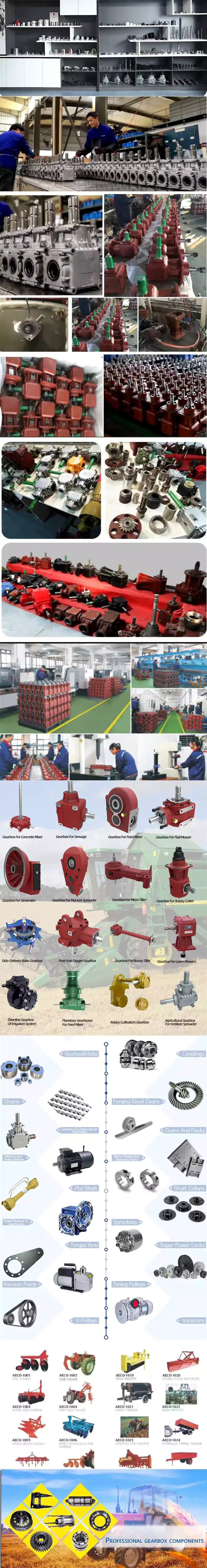
Our Manufacturing facility

Sample Area

Why select us?

one) Customization: With a sturdy R&D crew, and we can develop merchandise as essential. It only requires up to 7 days for us to design and style a established of drawings. The manufacturing time for new merchandise is typically 50 times or much less.

two) Good quality: We have our personal total inspection and testing tools, which can ensure the high quality of the goods.

3) Potential: Our annual creation ability is in excess of five hundred,000 sets, also, we also take little quantity orders, to satisfy the requirements of diverse customer’s obtain quantities.

four) Services: We concentrate on offering high-top quality products. Our merchandise are in line with worldwide requirements and are mostly exported to Europe, Australia, and other countries and areas.

5) Shipment: We are shut to HangZhou and ZheJiang ports, to offer the swiftest delivery support.
 

Packaging & Transport

FAQ

Q: Are you a investing business or producer?
A: We’re manufacturing facility and providing gearbox ODM & OEM providers for the European market place for far more than ten years

Q: Do you provide samples? is it free or further?
A: Sure, we could supply the sample for cost-free demand but do not shell out the cost of freight.

Q: How lengthy is your shipping and delivery time? What is your phrases of payment?
A: Generally it is 40-45 times. The time could differ depending on the product and the level of customization.
For regular items, the payment is: 30% T/T in advance,balance just before cargo.

Q: What is the exact MOQ or price tag for your item?
A: As an OEM firm, we can offer and adapt our goods to a broad range of needs.
Thus, MOQ and price tag might tremendously range with dimensions, content and even more technical specs For instance, expensive goods or common merchandise will typically have a reduce MOQ. Make sure you get in touch with us with all related particulars to get the most precise quotation.

If you have an additional question, you should come to feel free of charge to get in touch with us.

US $10-300
/ Piece
|
1 Piece

(Min. Order)

###

Application: Machinery, Agricultural Machinery
Function: Distribution Power, Change Drive Torque, Change Drive Direction, Speed Changing, Speed Reduction, Speed Increase
Layout: Straight or Spiral Bevel Gear
Hardness: Hardened Tooth Surface
Installation: Vertical Type
Step: Single-Step

###

Customization:

Choosing the Right Agricultural Gearbox

When buying an agricultural gearbox, there are a few things to consider. The quality of materials, functionality, and mechanism are crucial factors to durability. A durable device will ensure that you won’t have to keep replacing it. Here are some tips to help you select the right one. Let’s begin. Read on to learn more about the different features available in agricultural gearboxes. Listed below are a few of the most important factors to consider.
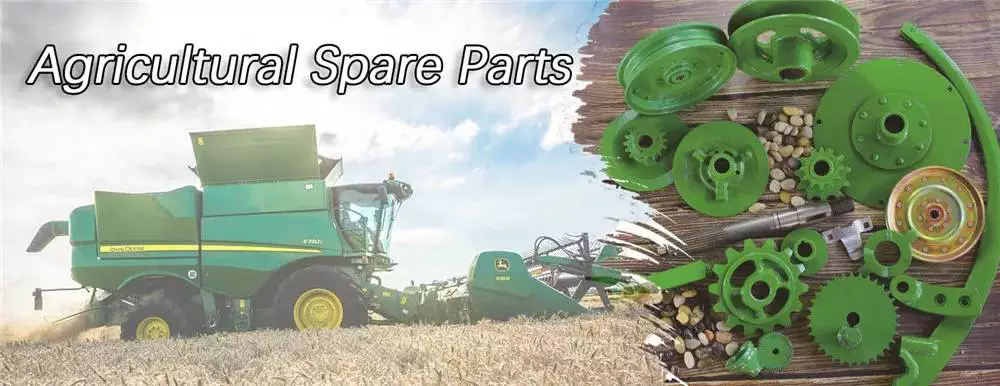
agriculturalparts

Bevel gearboxes

Agricultural gearboxes are essential to the entire food cycle. If your gears are not in good shape, you will be unable to meet the demand and you will suffer from heightened downtime. Fortunately, there are numerous quality bevel gearboxes available on the market today. In fact, the CZPT Gearbox Company supplies bevel gearboxes for agricultural applications. Here are some of the reasons you should choose the right one.
A bevel gearbox is a single-stage unit that interlocks bevelled edges on two gears to transfer torque and rotation. These gears can be either straight or helical. This type of gearbox is inexpensive to produce and operates quietly. It also has lower transmittable torque. Bevel gearboxes are often used as a low-cost alternative to hypoid gearboxes.
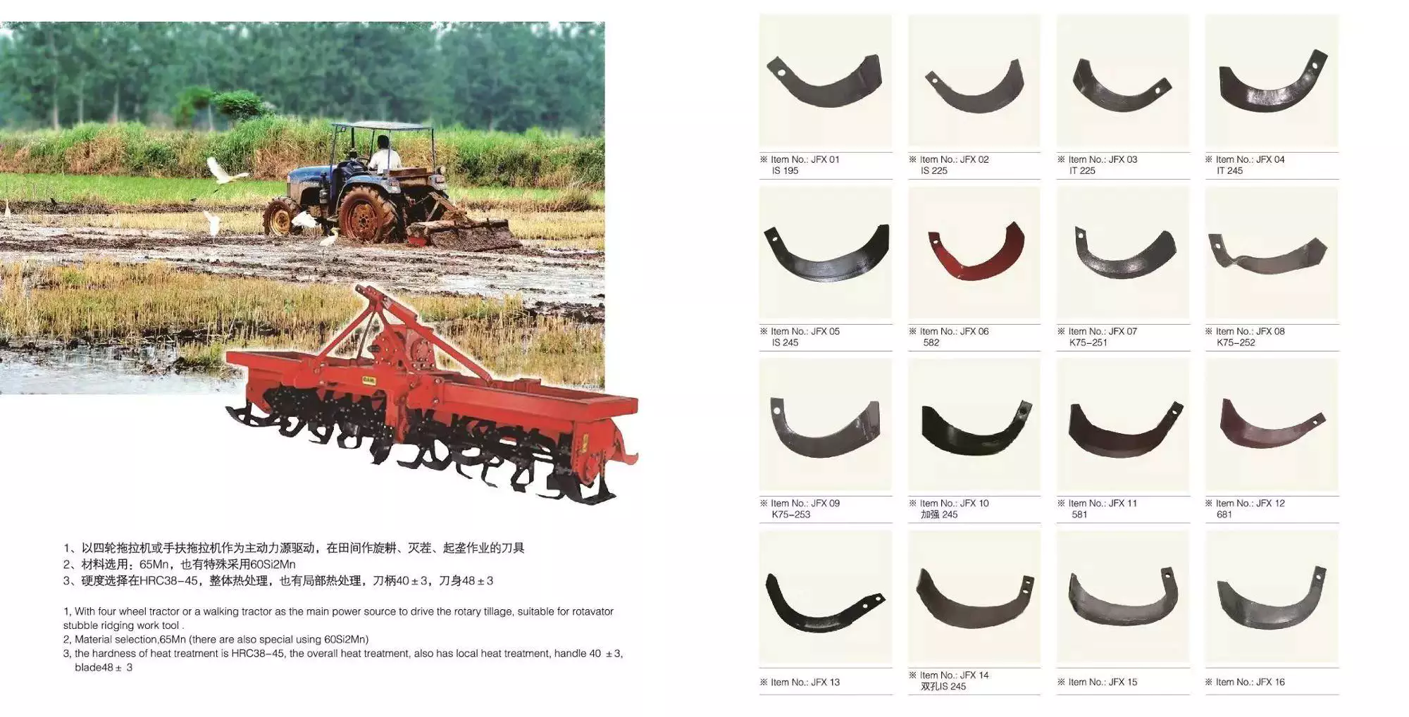
Agricultural bevel gearboxes are used in various applications, including hay balers, combine harvesters, seeders, and plows. These gears are well-suited for use with offset rotary fillers. They offer reduction ratios of up to 2.44 and cast iron cases. They are commonly known as “right-angle gearboxes” or “Parallel SHAFT gearboxes.”
Agricultural bevel gearboxes come in many sizes and ratios. In general, higher sizes are made of closed-grain cast-iron. Other materials, such as SG 500/7, are used for larger sizes. The main gear and each drive gear are mesh-mounted, and the shafts are designed to rotate in either direction. They have oil seals on the joints. The Spiral Bevel Gearbox is best suited for FG60 or FG75 motors.
The RINV-OP65 right-angle angular gearbox comes with an optional electronic or mechanical position indicator. Its angular design allows for changes in axis rotation, and provides smooth power transmission with minimal backlash. Premium gearmotors include hardened spiral bevel gears and stainless steel shafts for quiet operation. They are available in various ratios and shaft styles. If you want to choose one, make sure it is made to fit the needs of the machine.

Closed-loop seals

There are a number of reasons to install closed-loop seals in an agricultural gearbox. The first is the need to isolate the gearbox from the atmosphere, an important safety concern. Closed-loop seals are CZPT alternatives to desiccant breathers because they prevent the entry of water. While these seals can’t keep the gearbox underwater, they isolate the gearbox from the atmosphere and are therefore vital for the safety of your equipment.
The most common material used for these seals is polymer rubber. Most are made from HBR, which stands for High-cis polybutadiene rubber. Other materials include Butadiene and FKM, which are known for their high-temperature performance. However, the disadvantage of these seals is that they are susceptible to shaft damage and degrade quickly in high temperatures. Therefore, you should always consider the type of seal before purchasing one.
If you plan to use agricultural gearboxes on a regular basis, you should consider getting a good quality one. You should look for a closed-loop seal on your gearbox to protect it against dirt and debris. A quality agricultural gearbox also has an easy-access design, which will make it easy to access and maintain. This will ensure its long-lasting performance and low-maintenance costs.
Agricultural equipment is frequently used to perform various tasks, such as sowing seeds, spreading fertilizer, digging holes, and more. This requires durable and effective sealing solutions to keep dirt out of the system and lubricants in. A close-loop seal helps to ensure that all these operations are performed at maximum efficiency. If you’re a farmer, closed-loop seals are the ideal solution for you.
agriculturalparts

Surface finish

The surface finish of an agricultural gearbox should be free from defects in the casting process and mechanical damage. The bearing hole in the shaft must be a minimum of 100 mm long and the distance between the bearing holes should be equal to the shaft length. The shaft should be free of any cracks or burrs. The ellipticity and centerline irregularity of the shaft must be less than 0.015 mm. Likewise, the diameter of the shaft, hole spacing and bearing hole relationship should be at least 20 mm.
In recent studies, researchers have investigated the efficiency of different surfaces on the same materials. They found that surface roughness affects gearbox efficiency. Kahraman et al. reported that superfinishing the gears and reducing surface roughness improved efficiency. In addition, Andersson et al. investigated the impact of different assembly processes on the gearbox’ surface roughness. The results of their studies are presented in Table I.
The quality of the surface finish of an agricultural gearbox depends on the materials used. A typical example is wrought steel gear. The die inserts for a forged gear were made of H11 or H13 tool steel. This material softens over time and has a limited life span. An improved alternative was Alloy 718. This alloy has a high temperature range and is suitable for high rotational speeds.
A good surface finish is vital for the health and safety of an agricultural gearbox. It protects the entire food chain and is necessary for agricultural production. The heightened demand for food will cause increased wear and tear on farm machinery. Moreover, a damaged gear will cost the farmer a lot of money. Therefore, it is crucial for farmers to invest in a high-quality agricultural gearbox to avoid such costly downtimes.

Shaft arrangement

An agricultural gearbox has two main stages, the first of which is the reduction stage. The reduction stage contains the pinion, a series of gears, and the first reduction stage. A second stage is connected to the first reduction stage via a mechanical clutch. This gearbox typically consists of three stages. The first reduction stage is also known as the low gear “L”. The first reduction stage provides four forward gearing ratios, while the second stage has three forward gearing ratios. A conventional agricultural gearbox also incorporates a mechanical clutch.
The second stage is a speed change gearbox. It has an input and output shaft. The input shaft is rotatably mounted in the casing and extends through the tractor’s interior. The shaft extends to the rear of the tractor, where the driven part of the joint 26 is keyed onto. The rear end portion of the shaft projects into the back axle casing 15, where it is connected to the first transmission shaft 34. The gearbox then serves to drive the power take-off shaft 36.
Newer types of tractors have larger shafts to support higher power applications. Type 3 tractors have a larger shaft with 20 splines while Type 2 tractors have a smaller shaft. The Type 2 is often referred to as the small 1000. When viewed from inside the tractor cab, Type 3 and Type 2 are rotated counterclockwise. If you are unfamiliar with agricultural gearboxes, here are some basic terms.
Shaft arrangement is important in choosing the right gearing system for agricultural machinery. There are a few differences between these arrangements. The first type has a higher gear ratio, while the second has lower. In terms of speed, the shaft arrangement of an agricultural gearbox reflects the speed of the machinery. The higher the speed of the gear, the higher the output speed. So, when choosing a gearbox, keep this in mind.
agriculturalparts

Cost

Purchasing an agricultural gearbox may be a costly process, but the benefits outweigh the price. Agricultural gearboxes are vital to the food cycle. When a gear breaks down, farmers will face significant losses. Additionally, agricultural applications use a high-quality gearbox to minimize equipment wear and tear. Ultimately, a high-quality gearbox will reduce the cost of production while extending the lifespan of the agricultural machinery.
Many countries trade in Agriculture Gearbox with India, and many of these suppliers are located in India. Using a marketplace to buy from Indian suppliers offers several advantages. Among the many factors to consider when choosing an Agriculture Gearbox supplier are quality, price, reliability, and past trade history. Through a marketplace like CZPT, you can obtain 360-degree information on Indian Agriculture Gearbox suppliers. In this way, you can choose a vendor with whom you do business.
CZPT Gearbox Company is a leading manufacturer of high-quality agricultural gearboxes. Their experienced engineers can reverse-engineer an existing design for a custom-made gearbox for your needs. Whether you need a smaller or larger gearbox for an agricultural application, CZPT Gearbox Company is your partner. A line of high-quality agricultural gearboxes from CZPT Gearbox Company will help you maximize the performance of your farm machinery. They will transfer rotational power from the input shaft to the output shafts, allowing for a change in speed, direction, and rotation.
China Right Angle Gear Box Pto Farm Rotary Slasher Feeder Mixer Rotary Tiller Cultivator Baller Tractor Agricultural Machinery Parts Bevel Gearbox     agricultural gearboxes	China Right Angle Gear Box Pto Farm Rotary Slasher Feeder Mixer Rotary Tiller Cultivator Baller Tractor Agricultural Machinery Parts Bevel Gearbox     agricultural gearboxes
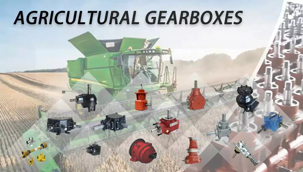
editor by czh 2023-01-29

China Stepless Worm Gear Reduction Gearbox with Good Service for Agricultural Machinery farm tractor transmission types

Item Description

Solution Description

Merchandise Parameters

Packaging & Shipping

Business Profile

To Be Negotiated 1 Piece
(Min. Order)

###

Application: Motor, Electric Cars, Motorcycle, Machinery, Marine, Toy, Agricultural Machinery, Car
Hardness: Soft Tooth Surface
Installation: 90 Degree
Layout: Coaxial
Gear Shape: Conical – Cylindrical Gear
Step: Stepless

###

Customization:
To Be Negotiated 1 Piece
(Min. Order)

###

Application: Motor, Electric Cars, Motorcycle, Machinery, Marine, Toy, Agricultural Machinery, Car
Hardness: Soft Tooth Surface
Installation: 90 Degree
Layout: Coaxial
Gear Shape: Conical – Cylindrical Gear
Step: Stepless

###

Customization:

Agricultural Gearboxes

There are several types of agricultural gearboxes, and they are used in various applications. Among them are Bevel gearboxes, CZPT speed gearboxes, and Worm gear speed reducers. If you’re looking for a reliable, high-performing agricultural gearbox, you’ve come to the right place. Read on to learn more about these gearboxes. Also, check out our guide to bevel gearboxes.
agriculturalparts

Bevel gearboxes

The fatigue life of bevel gearboxes in agricultural equipment is determined by the cumulative damage sums for different operations. A simulation model was used to assess the fatigue life of a spiral bevel gear. The accumulated damage sums for each operation were shown in figure 9a. The subsoiler tillage operation exceeded the damage sum of one. This criterion indicates that the fatigue life of a gearbox is shorter than its service life.
In bevel gearboxes, the second shaft has two shafts that are connected to each other. One shaft is mounted to the outer surface of the housing 3 through bearings, while the other shaft has a flange that protrudes into the gear housing. The second shaft is attached via bearings on the gear housing and flange. It is mounted in this way to allow the bevel gear to rotate smoothly.
agriculturalparts

CZPT speed gearboxes

If you are an agricultural machine owner, you know that the right speed agricultural gearboxes can make the difference between a profitable crop harvest or a disaster. Today’s agricultural machinery can be found in a variety of applications, including for crop and animal production. Many of these applications require heavy-duty gearboxes with large capacity. The quality of these agricultural gearboxes depends on the quality of their bearings, which are important to the longevity of your equipment.
Industrial CZPT gearboxes can be repaired and overhauled by qualified and experienced technicians at CZPT Products. CZPT gearboxes can be repaired or rebuilt at significant savings. For industrial uses, the RAR model is perfect for applications where space is a consideration. Industrial CZPT gearboxes are available in multiple sizes and types, and they can be customized to meet your unique needs. For the best price and service, contact CZPT Products today!
agriculturalparts

CZPT speed bevel gearboxes

The demand for food has skyrocketed since the 2010 global financial crisis, and while the world’s population is still rising, at a slower rate, land is not. This is forcing agricultural machinery manufacturers to come up with innovative solutions to maximize the use of available land. The need for agricultural machinery is also growing due to shorter cropping cycles and wear and tear on equipment. CZPT gearbox manufacturers are meeting this demand with high-quality products.
A number of benefits make CZPT speed bevel gearboxes the preferred choice for agricultural applications. In addition to its renowned performance, the product’s design has been adapted for use in agricultural and glass machinery. The result is a unit with low backlash and high transmission. Moreover, the CZPT model is the best all-rounder among servo right-angle gearboxes.
China Stepless Worm Gear Reduction Gearbox with Good Service for Agricultural Machinery     farm tractor transmission types	China Stepless Worm Gear Reduction Gearbox with Good Service for Agricultural Machinery     farm tractor transmission types
editor by czh 2023-01-26

China high quality agricultural machinery farm equipment tractor rotary tiller wholesaler

Condition: New
Type: Farm Cultivator
Electrical power Variety: Diesel
Machine Variety: Rotary Tiller
Warranty: 1 Yr
Important Marketing Points: Large Efficiency
Marketing and advertising Sort: New Product 2571
Equipment Take a look at Report: Not Accessible
Video clip outgoing-inspection: Provided
Warranty of core factors: 1 Year
Core Factors: Gear
Relevant Industries: Farms
Showroom Place: None
item: agricultural machinery/ farm products/ tractor rotary tiller
Right after-sales Support Provided: On the internet assist
Following Warranty Provider: On-line support
Local Service Location: None
Certification: ISO
Packaging Specifics: nude
Port: ZheJiang

Advise Goods Packing & Shipping

packaging genuine packaging
according to customers’ ask for
nude packaging
standard export pacakging
shipping by convey DHL, FEDEX, UPS, TNT, ect.
by air China principal port
by sea China main port
payment TT, western union, credit card, Alibaba trade assurance, ect.

Organization Profile ZheJiang  Grande Machinery Manufacturing Co. Appropriate Angle Gearbox Substantial Precision Planetary Equipment Reducer  Ltd. focuses on tractors, harvesters, rice transplanters, tractor equipment, harvester accessories and other agricultural machineries. at present the major manufacturers are KUBOTA,WORLD, YANMAR, YTO, and so on. Sufficient stock.Our organization has thirty personnel, a thousand sq. meters of office spot and 7000 sq. meters of warehouse, Adhering to the principle of consumer first, in purchase to supply better specialized assist and right after-income support, the business experienced established a complex department and after-revenue provider section in 2018.ZheJiang  Grande  Hammer Crusher Component Hammer Blade Hardfacing Tungsitn Carbide Beaters Machinery Manufacturing Co. Ltd. offers clients with one-end answers! FAQ one. What is actually the MOQ?1 established of the machine. relating to the spare components, make sure you validate with salesperson.2. What’s your shipping and delivery time and shipping and delivery way?devices: 15 operate times in off seasons, thirty times in CZPT seasons, shipped by sea.spare elements: in accordance to the amount and objects. shipped by specific or sea.3. What is actually your Payment phrases?30% advanced payment, 70% equilibrium payment ahead of supply by T/T or credit card.4. What is actually the after income of the machine?Our items warranty is twelve months. soon after that, we can also offer spare parts, Agricultural Gear box Green Place Drive Power Tiller Appropriate Angle Agriculture Tractor Pto Bevel Flail Mower Gearbox For Gardening but not for free of charge.Lifelong cost-free technical assist.If you have any other queries, make sure you make contact with with salesperson straight. Make contact with Us

Axle Spindle Types and Features

The axle spindle is an integral part of your vehicle’s suspension. There are several different types and features, including mounting methods, bearings, and functions. Read on for some basic information on axle spindles. The next part of the article will cover how to choose the correct axle spindle for your vehicle. This article will also discuss the different types of spindles available, including the differences between the rear and front bearings.
Driveshaft

Features

The improved axle spindle nut assembly is capable of providing additional performance benefits, including increased tire life and reduced seal failure. Its keyway features and radially inwardly extending teeth allow nut adjustment to be accomplished with precision. The invention further provides a unique, multi-piece locking mechanism that minimizes leakage and torque transfer. Its principles and features are detailed in the appended claims. For example, the improved axle spindle nut assembly is designed for use in vehicles that are equipped with a steering system.
The axle spindle nut assembly includes a nut 252 with threads 256 on its inner periphery. The axle spindle 50 also features threads 198 on its outer periphery. The nut is threaded onto the outboard end of the axle spindle 50 until it contacts the inboard surface of the axle spacer 26. In the assembled state, a bearing spacer 58 is also present on the axle spindle.
The axle spindle nut assembly can reduce axial end play between the wheel end assembly 52 and the axle spindle 50. It can be tightened to an extreme torque level, but if the thread faces separate, it will undercompress the bearing cone and spacer group. To minimize these disadvantages, the axle spindle nut assembly is a critical component of a wheel-end assembly. There are several types of axle spindle nuts.
The third embodiment of the axle spindle nut assembly 300 comprises an inner washer 202, an outer washer 310, and at least one screw 320. The axle spindle nut assembly 300 secures and preloads bearing cones 55, 57. Unlike the first embodiment, the axle spindle nut assembly 300 uses the inner washer 202, which is optional in the third embodiment. The inner washer 202 and outer washer 310 are similar to those of the first embodiment.

Functions

An axle spindle is one of the most important components of a vehicle’s suspension system. The spindle retains the position of bearings and a spacer in an axle by providing clamp force. The inner nut of an axle spindle should be properly torqued to ensure a secure fit. A spindle nut is also responsible for compressing bearings and spacers. If any of these components are missing, the spindle will not work properly.
An axle spindle is used in rear wheel drive cars. It carries the weight of the vehicle on the axle casing and transfers the torque from the differential to the wheels. The axle spindle and hub are secured on the spindle by large nuts. The axle spindle is a vital component of rear wheel drive vehicles. Hence, it is essential to understand the functions of axle spindle. These components are responsible for the smooth operation of a vehicle’s suspension system.
Axle spindles can be mounted in three ways: in the typical axle assembly, the spindles are bolted onto the ends of the tubular axle, and the axle is suspended by springs. Short stub-axle mounting uses a torsion beam that flexes to provide a smooth ride. A second washer is used to prevent excessive rotation of the axle spindle.
Apart from being a crucial component of the suspension system, the spindles of the wheels are responsible for guiding the vehicle in a straight line. They are connected to the steering axis and are used in different types of suspension systems. European cars use a MacPherson Strut suspension system in which the spindle is connected to the arms in the front and rear of the suspension frame. The MacPherson strut allows the shock absorber housing to turn the wheel.
Driveshaft

Methods of mounting

Various methods of mounting axle spindle are available. In general, these methods involve forming a tubular blank of uniform cross section and thickness, and receiving the bearing assembly against it. The spindle is then secured using a collar, which also serves as a bearing stop. In some cases, additional features are used to provide greater security. Some of these features may not be suitable for all applications. But they are generally suitable.
Axle spindle forming is usually done by progressive steps using hollow punches. The metallic body of the punch has an inner work surface, which receives the axle blank. A mandrel is fixed within the work opening of the punch. The punch body’s work surface forges the spindle about the mandrel. The punch has two ends, a closed and an open one.
A wheeled vehicle axle assembly (10) includes a cylindrical housing member (12 a) and a plurality of spindle mounting flanges (30) secured on the housing member. The spindles (16) are firmly attached to the housing member by means of coupling members. The coupling members are configured to distribute the bending loads imposed on the spindle by the axle. It is important to note that the coupling members can be either threaded or screwed.
Traditionally, axle spindles were made from tubular blanks of irregular thickness. This method allowed for a gradual reduction in diameter and eliminated the need for extra metal within the spindle. Similarly, axles made by cold forming eliminate the need for additional metal in the spindle. In this way, the overall cost of manufacture is also reduced. The material used for manufacturing axles also determines the size and shape of the final product.
Driveshaft

Bearings

A nut 16 is used to retain the wheel bearings on axle spindle 12. The nut comprises several parts. The first portion includes a plurality of threads and a deformable second portion. The nut may be disposed on the inboard or outboard end of the axle spindle. This type of nut is typically secured to the axle spindle by a retaining nut.
The bearings are installed in the spindle to allow the wheel hub to rotate. While bearings are greased, they can dry out over time. Consequently, you may hear a loud clicking sound when turning your vehicle. Alternatively, you may notice grease on the edges of your tires. Bearing failure can cause severe damage to your axle spindle. If you notice any of these symptoms, you may need to replace the bearings on your axle spindle. Fortunately, you can purchase the necessary bearing parts at O’Reilly Auto Parts.
There are three ways to mount an axle spindle. A typical axle assembly has the spindles bolted to the ends of the tubular axle. A torsion beam is also used to mount the spindles on the axle. This torsion beam acts like a spring to help make the ride smooth and bump-free. Lastly, the axle spindle is sometimes mounted as a bolt-on component.

Cost

If your axle spindle has been damaged, you may need to have it replaced. This part of the axle is relatively easy to replace, but you need to know how to do it correctly. To replace your axle spindle, you must first remove the damaged one. To do this, a technician will cut the weld. They will then thread the new one into the axle tube and torque it to specification. After that, they will weld the new axle spindle into place.
When you are thinking about the cost of an axle spindle replacement, you must first determine if it is worth it for your vehicle. It is generally a good idea to replace the spindle only if it is causing damage to your vehicle. You can also replace your axle housing if it is deteriorating. If you do not replace the spindle, you can risk damaging the axle housing. To save money, you can consider using a repair kit.
You can also purchase an axle nut socket set. Most wrenches have an adjusting socket for this purpose. The socket set should be suitable for most vehicle types. Axle spindle replacement costs around $500 to $600 before tax. However, you should be aware that these costs vary widely based on the type of vehicle you have. The parts can cost between $430 and $480, and the labor can cost anywhere from $50 to 70.

China high quality agricultural machinery farm equipment tractor rotary tiller     wholesaler

China OEM 110HP 4WD Farm Machinery Agricultural Tractor wholesaler

Product Description

Weichai Deutz six cylinder engine(turbocharger,intercooling) is designed with 12 hours rated power(82kw), fully enclosed cab, air heater, 16+4 shifts of transmission, shifting synchronizer, integrated frame, driving system with modularized structure,DANA front axle,construction machinery rear axle, caliper disc brake, replaceable power output shaft, revolution for power output shaft of dual revolution 540/1000r/min, fully hydraulic front wheel steering, two groups of hydraulic output, plough depth control method by position, floating control, and suspension mechanism of rear-mounted Category II.

Main Features:
 
A. Easy to add accessories  
With integrated frame and independent expandable PTO may easily add such accessories as loading, excavation, bulldozing, well digging, and lifting etc. to expand functions of tractor and increase utilization rate of tractor.
 
B. Easy to utilize matured technology
Adoption of matured technology in loading truck, engineering machinery, and other industry may directly be made for product components. For example, application of such technologies as caliper disc brake, wet clutch, synchronizer, fuel and gas booster etc may accelerate to upgrade technology of large-power tractor products relying on developing advantages in the other industries.

C. Easy to expand portfolio of product
Adoption of matured products from loading truck, engineering machinery, and agricultural machinery are made for the components. For each type of product, different series of specification have been designed. Optimized portfolios of these series of components have formed products with different power ranges, which may greatly reduce developing cycle of products. Over four years, eight models with more than 30 variants have totally been developed by 110-280 HP in successively, where mass production has been made for six models.

D. Easy to meet user’ requirement of individualization 
Adjustment of speed ratio of transfer box may have different speed with different shifts to meet agricultural requirements of refinement in different areas. Adjustment of speed ratio of final transfer box may meet the requirements of downstream output rpm against different countries. The tractors may be customized according to user’s requirements against functional modules.

E. Easy to organize mass production
Adoption of general components has been made for modularized structures to fully utilize social resources and professionalized production and manufacturing platform in C. Large-scale fixed assets is unnecessarily invested to produce wheel type of large tractor with high power in mass production, which may change traditional production organization method of tractor and solve current production bottleneck for production of large traditional tractor.

F. Easy to Service
All possible defects can easily be found and easy maintenance may be made due to modularized structure.
 

Model   KAT1104
Engine Power/speed kW/r/min 82(110)/2200
Specific Fuel Consumption g/kw.h ≤225
Drive Type    / 4×4
Dimension(Length/Width/Height) mm 5090/2160/3040
Wheel Base mm 2688
Track(Front wheel) mm 1552-1948
Track(Rear wheel) mm 1626-2150
Min. Ground Clearance mm 450
Min.running weight kg 5700
Front counter weight kg 300
Rated Traction Force kN 26
No. of gear   16F+4R
Forward Gear Speed km/h 3-32
Reverse Gear Speed km/h 6-27
Tyre Model Front Tires    / 14.9-24
Rear Tires    / 16.9-38
Power-output shaft Type    / Rear position or independent
Power-output shaftRated Speed r/min 540/1000
Max. Pull-down piston pull kN 25

Stiffness and Torsional Vibration of Spline-Couplings

In this paper, we describe some basic characteristics of spline-coupling and examine its torsional vibration behavior. We also explore the effect of spline misalignment on rotor-spline coupling. These results will assist in the design of improved spline-coupling systems for various applications. The results are presented in Table 1.
splineshaft

Stiffness of spline-coupling

The stiffness of a spline-coupling is a function of the meshing force between the splines in a rotor-spline coupling system and the static vibration displacement. The meshing force depends on the coupling parameters such as the transmitting torque and the spline thickness. It increases nonlinearly with the spline thickness.
A simplified spline-coupling model can be used to evaluate the load distribution of splines under vibration and transient loads. The axle spline sleeve is displaced a z-direction and a resistance moment T is applied to the outer face of the sleeve. This simple model can satisfy a wide range of engineering requirements but may suffer from complex loading conditions. Its asymmetric clearance may affect its engagement behavior and stress distribution patterns.
The results of the simulations show that the maximum vibration acceleration in both Figures 10 and 22 was 3.03 g/s. This results indicate that a misalignment in the circumferential direction increases the instantaneous impact. Asymmetry in the coupling geometry is also found in the meshing. The right-side spline’s teeth mesh tightly while those on the left side are misaligned.
Considering the spline-coupling geometry, a semi-analytical model is used to compute stiffness. This model is a simplified form of a classical spline-coupling model, with submatrices defining the shape and stiffness of the joint. As the design clearance is a known value, the stiffness of a spline-coupling system can be analyzed using the same formula.
The results of the simulations also show that the spline-coupling system can be modeled using MASTA, a high-level commercial CAE tool for transmission analysis. In this case, the spline segments were modeled as a series of spline segments with variable stiffness, which was calculated based on the initial gap between spline teeth. Then, the spline segments were modelled as a series of splines of increasing stiffness, accounting for different manufacturing variations. The resulting analysis of the spline-coupling geometry is compared to those of the finite-element approach.
Despite the high stiffness of a spline-coupling system, the contact status of the contact surfaces often changes. In addition, spline coupling affects the lateral vibration and deformation of the rotor. However, stiffness nonlinearity is not well studied in splined rotors because of the lack of a fully analytical model.
splineshaft

Characteristics of spline-coupling

The study of spline-coupling involves a number of design factors. These include weight, materials, and performance requirements. Weight is particularly important in the aeronautics field. Weight is often an issue for design engineers because materials have varying dimensional stability, weight, and durability. Additionally, space constraints and other configuration restrictions may require the use of spline-couplings in certain applications.
The main parameters to consider for any spline-coupling design are the maximum principal stress, the maldistribution factor, and the maximum tooth-bearing stress. The magnitude of each of these parameters must be smaller than or equal to the external spline diameter, in order to provide stability. The outer diameter of the spline must be at least four inches larger than the inner diameter of the spline.
Once the physical design is validated, the spline coupling knowledge base is created. This model is pre-programmed and stores the design parameter signals, including performance and manufacturing constraints. It then compares the parameter values to the design rule signals, and constructs a geometric representation of the spline coupling. A visual model is created from the input signals, and can be manipulated by changing different parameters and specifications.
The stiffness of a spline joint is another important parameter for determining the spline-coupling stiffness. The stiffness distribution of the spline joint affects the rotor’s lateral vibration and deformation. A finite element method is a useful technique for obtaining lateral stiffness of spline joints. This method involves many mesh refinements and requires a high computational cost.
The diameter of the spline-coupling must be large enough to transmit the torque. A spline with a larger diameter may have greater torque-transmitting capacity because it has a smaller circumference. However, the larger diameter of a spline is thinner than the shaft, and the latter may be more suitable if the torque is spread over a greater number of teeth.
Spline-couplings are classified according to their tooth profile along the axial and radial directions. The radial and axial tooth profiles affect the component’s behavior and wear damage. Splines with a crowned tooth profile are prone to angular misalignment. Typically, these spline-couplings are oversized to ensure durability and safety.

Stiffness of spline-coupling in torsional vibration analysis

This article presents a general framework for the study of torsional vibration caused by the stiffness of spline-couplings in aero-engines. It is based on a previous study on spline-couplings. It is characterized by the following three factors: bending stiffness, total flexibility, and tangential stiffness. The first criterion is the equivalent diameter of external and internal splines. Both the spline-coupling stiffness and the displacement of splines are evaluated by using the derivative of the total flexibility.
The stiffness of a spline joint can vary based on the distribution of load along the spline. Variables affecting the stiffness of spline joints include the torque level, tooth indexing errors, and misalignment. To explore the effects of these variables, an analytical formula is developed. The method is applicable for various kinds of spline joints, such as splines with multiple components.
Despite the difficulty of calculating spline-coupling stiffness, it is possible to model the contact between the teeth of the shaft and the hub using an analytical approach. This approach helps in determining key magnitudes of coupling operation such as contact peak pressures, reaction moments, and angular momentum. This approach allows for accurate results for spline-couplings and is suitable for both torsional vibration and structural vibration analysis.
The stiffness of spline-coupling is commonly assumed to be rigid in dynamic models. However, various dynamic phenomena associated with spline joints must be captured in high-fidelity drivetrain models. To accomplish this, a general analytical stiffness formulation is proposed based on a semi-analytical spline load distribution model. The resulting stiffness matrix contains radial and tilting stiffness values as well as torsional stiffness. The analysis is further simplified with the blockwise inversion method.
It is essential to consider the torsional vibration of a power transmission system before selecting the coupling. An accurate analysis of torsional vibration is crucial for coupling safety. This article also discusses case studies of spline shaft wear and torsionally-induced failures. The discussion will conclude with the development of a robust and efficient method to simulate these problems in real-life scenarios.
splineshaft

Effect of spline misalignment on rotor-spline coupling

In this study, the effect of spline misalignment in rotor-spline coupling is investigated. The stability boundary and mechanism of rotor instability are analyzed. We find that the meshing force of a misaligned spline coupling increases nonlinearly with spline thickness. The results demonstrate that the misalignment is responsible for the instability of the rotor-spline coupling system.
An intentional spline misalignment is introduced to achieve an interference fit and zero backlash condition. This leads to uneven load distribution among the spline teeth. A further spline misalignment of 50um can result in rotor-spline coupling failure. The maximum tensile root stress shifted to the left under this condition.
Positive spline misalignment increases the gear mesh misalignment. Conversely, negative spline misalignment has no effect. The right-handed spline misalignment is opposite to the helix hand. The high contact area is moved from the center to the left side. In both cases, gear mesh is misaligned due to deflection and tilting of the gear under load.
This variation of the tooth surface is measured as the change in clearance in the transverse plain. The radial and axial clearance values are the same, while the difference between the two is less. In addition to the frictional force, the axial clearance of the splines is the same, which increases the gear mesh misalignment. Hence, the same procedure can be used to determine the frictional force of a rotor-spline coupling.
Gear mesh misalignment influences spline-rotor coupling performance. This misalignment changes the distribution of the gear mesh and alters contact and bending stresses. Therefore, it is essential to understand the effects of misalignment in spline couplings. Using a simplified system of helical gear pair, Hong et al. examined the load distribution along the tooth interface of the spline. This misalignment caused the flank contact pattern to change. The misaligned teeth exhibited deflection under load and developed a tilting moment on the gear.
The effect of spline misalignment in rotor-spline couplings is minimized by using a mechanism that reduces backlash. The mechanism comprises cooperably splined male and female members. One member is formed by two coaxially aligned splined segments with end surfaces shaped to engage in sliding relationship. The connecting device applies axial loads to these segments, causing them to rotate relative to one another.